Method for detecting initial position of rotor of permanent magnet motor

A technology of rotor initial position and rotor position, applied in the direction of motor, control generator, motor generator control, etc., can solve the problems of increasing system complexity and implementation difficulty, avoiding repeated trial and error process, improving efficiency, reducing The effect of computation

Active Publication Date: 2021-05-11
BEIHANG UNIV
View PDF5 Cites 1 Cited by
  • Summary
  • Abstract
  • Description
  • Claims
  • Application Information

AI Technical Summary

Problems solved by technology

The accuracy of the high-frequency current injection method is not affected by the nonlinearity and dead zone of the inverter, but the current controller needs to have sufficient bandwidth and precision to track the high-frequency current signal. In addition, an additional voltage sensor needs to be added to increase the The complexity and implementation difficulty of the system

Method used


Image

  • Method for detecting initial position of rotor of permanent magnet motor
  • Method for detecting initial position of rotor of permanent magnet motor
  • Method for detecting initial position of rotor of permanent magnet motor

Examples


Embodiment Construction

[0036] The technical solution of the present invention will be further described in detail below in conjunction with the accompanying drawings.

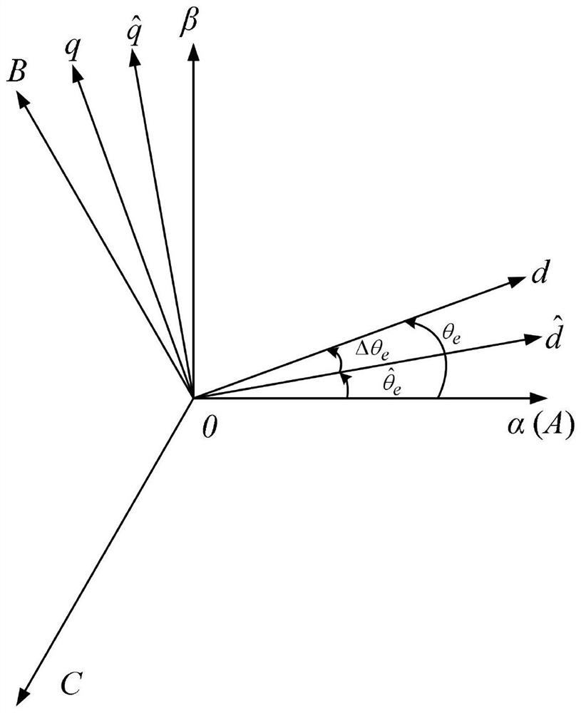
[0037] Such as figure 1 As shown, establish the two-phase stationary coordinate system α-β, the actual rotor synchronous rotating coordinate system d-q and the estimated rotor synchronous rotating coordinate system where the angle between the d-axis and the α-axis is the actual rotor position θ e , The angle between the α-axis and the α-axis is the estimated rotor position and

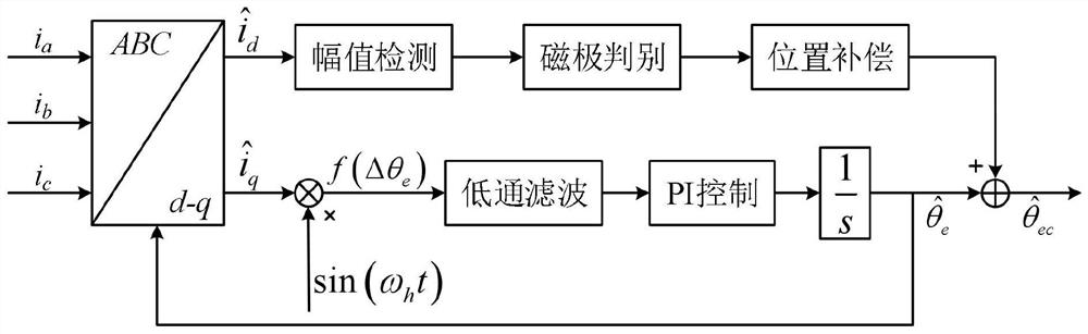
[0038] Such as figure 2 As shown, the permanent magnet motor rotor initial position detection method of the present invention comprises the following steps:

[0039] Step A) Initial estimation of rotor position: to the estimated The axis injects high-frequency carrier voltage, and collects Shaft carrier current and closed-loop control to realize the initial estimation of the rotor position;

[0040] Step B) Discrimination of the rotor magnetic...


PUM


Abstract

The invention discloses a method for detecting the initial position of a permanent magnet motor rotor, which belongs to the technical field of permanent magnet motor control and consists of three parts, namely initial estimation of the rotor position, discrimination of the magnetic pole direction of the rotor and compensation of the initial estimation of the rotor position. Firstly, high-frequency carrier voltage is injected into an estimated d axis, and initial estimation of the rotor position is achieved by collecting estimated q-axis carrier current and conducting closed-loop control. After initial estimation of the rotor position is completed, discrete Fourier transform is used to detect the amplitude of the carrier current so as to discriminate the magnetic pole direction of the rotor. And finally, the initial estimation value of the rotor position is compensated according to the discrimination result of the rotor magnetic pole direction to realize the detection of the initial position of the rotor. According to the invention, integration of initial estimation of the rotor position and a rotor magnetic pole direction discrimination algorithm is realized, the detection algorithm is simple, and the method has the advantages of fast detection speed and high reliability.

Description

technical field [0001] The invention relates to the field of motor control, in particular to a method for detecting the initial position of a rotor of a permanent magnet motor. Background technique [0002] Permanent magnet motors have the advantages of compact structure, high power density, good dynamic performance, and high efficiency, and have been used more and more widely. Real-time rotor position feedback is essential to achieve high-precision control of permanent magnet motors. Continuous rotor position information is usually obtained by using photoelectric encoders, resolvers and linear Hall sensors, and discrete rotor position information is obtained by using switching Hall sensors. However, these mechanical sensors may face the problems of difficult installation, difficult wiring, and poor reliability, so position sensorless control becomes an effective way to solve these problems. When the motor is running at medium or high speed, the position information of the...

Claims


Application Information

Patent Timeline
Patent Type & Authority Applications(China)
IPC IPC(8): H02P21/14H02P21/18H02P21/22H02P25/02
CPCH02P21/14H02P21/18H02P21/22H02P25/02Y02T10/64
Inventor 张海峰李海涛毛琨陈宝栋金浩郑世强
Owner BEIHANG UNIV
Why Eureka
Try Eureka