Postoperative drainage tube

A drainage tube and bile duct technology, applied in the direction of the catheter, can solve the problems of T-tube-related biliary fistula, tearing of the T-tube sinus, high pressure, etc. bit effect

Pending Publication Date: 2021-05-14
MENGCHAO HEPATOBILIARY HOSPITAL OF FUJIAN MEDICAL UNIV
View PDF13 Cites 0 Cited by
  • Summary
  • Abstract
  • Description
  • Claims
  • Application Information

AI Technical Summary

Problems solved by technology

Because the transverse cross-section of the "ˉ" part is larger than that of the "|" part, even after trimming, it still causes different degrees of difficulty and influence on the operation of the surgeon during the process of placing the bile duct
[0004] In addition, the T-shaped drainage tube usually needs to be removed at a later stage after successful placement. Since the transverse cross-section of the "ˉ" part is larger than the transverse cross-section of the "|" part, even if it has been trimmed and placed successfully before the bile duct is inserted, the When the tube is removed, because the pressure on the part where the drainage tube contacts the sinus is very high, it will damage or tear the T-tube sinus during rigid extraction, resulting in the risk of T-tube-related biliary fistula

Method used


Image

  • Postoperative drainage tube
  • Postoperative drainage tube
  • Postoperative drainage tube

Examples


Embodiment 1

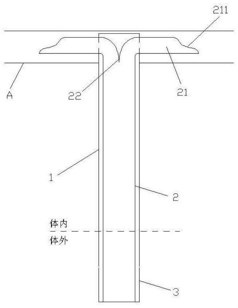
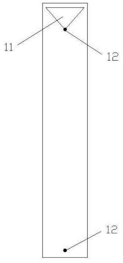
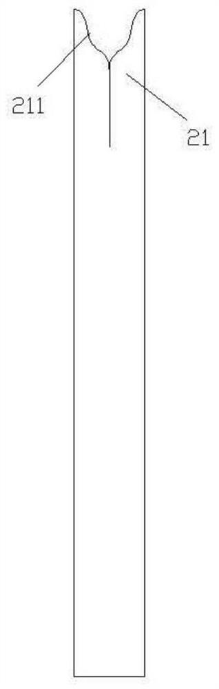
[0030] Provide a postoperative drainage tube designed to improve the integrity, stability and safety of traditional T-shaped drainage tubes as an entry point, such as figure 1 As shown: it includes an overtube 1 and a main drainage tube 2 arranged separately. The overtube 1 is used to extend into the bile duct A and the overtube is linear. The main drainage tube 2 is placed in the overtube 1 to enter the bile duct. The main drainage The tube 2 is the main part of the bile duct to drain bile, and the outer tube 1 mainly plays a connecting role. Among them, such as figure 2 and image 3 As shown, the end of the overtube 1 extending into the bile duct is respectively provided with through holes 11 on both sides of the bile flow direction in the bile duct, and the end of the main drainage tube 2 extending into the overtube 1 is a through hole that can be flexibly entered and pulled out. active fork structure.

[0031] The two forks 21 of the movable bifurcation structure are i...

Embodiment 2

[0044] The difference between this embodiment and embodiment 1 is: Figure 5 As shown, the main drainage tube 2 is provided with a circular drainage hole 24 below the junction of the fork and the pipe (the hole can also be opened at the junction of the fork and the pipe), and the diameter of the hole is about 3-4mm. within the radiation range of the through hole 11. The setting of the drainage hole 24 can further prevent the bile from leaking out. When the bile is discharged normally, most of the bile can flow smoothly along the fork to the external end of the main drainage tube and the intestinal tract at the lower end of the bile duct. A small amount of bile can also enter the outer cannula from the through hole 11 , this part of bile can be drained into the main drainage tube through the drainage hole. In addition, the outer cannula can also provide additional protection for the bile leaking from the main drainage tube, and finally achieve the smooth drainage of all bile. ...

Embodiment 3

[0046] like Figure 6 As shown, the difference between the present embodiment and Embodiment 1 is that the through hole 11 is a semicircular hole, and the straight side is also set near the end of the outer tube extending into the bile duct, the length of the straight side is equal to the diameter of the main drainage tube, and the through hole The height is equal to the radius of the main drain. Compared with the isosceles triangular hole, the drainage effect and safety of the semicircular hole are slightly inferior, but it can also better meet the drainage needs.


PUM


Abstract

The invention relates to the technical field of medical instruments, and discloses a postoperative drainage tube, which comprises an outer sleeve and a main drainage tube, which are arranged in a split mode. The outer sleeve stretches into a bile duct, the main drainage tube is arranged in the outer sleeve so as to enter the bile duct, and through holes are formed in the two ends, in the bile circulation direction in the bile duct, of the end, stretching into the bile duct, of the outer sleeve respectively. The end part, extending into the outer sleeve, of the main drainage tube is of a movable forked structure which can be flexibly inserted into and pulled out of the through holes. The integrated structure thought of a traditional T-shaped drainage tube is subverted, the drainage tube is designed in a split mode, only the linear outer sleeve is in direct contact with the bile duct wall, the main drainage tube stretches into the outer sleeve for drainage after the outer sleeve enters the bile duct, the main drainage tube is firstly withdrawn, then the outer sleeve is withdrawn, the drainage tube can be easily placed in and withdrawn from the bile duct, the bile duct and the sinus tract of the drainage tube are prevented from being damaged, the drainage tube is prevented from shifting, in addition, the main drainage tube can be placed in the outer sleeve after the outer sleeve is in place and the bile duct is sutured, and the main drainage tube is effectively prevented from being sutured.

Description

technical field [0001] The invention relates to the technical field of medical devices, in particular to a postoperative drainage tube for bile drainage. Background technique [0002] Medical T-shaped drainage tubes are widely used in the drainage of extrahepatic and extrahepatic bile ducts after hepatobiliary surgery. 3) promote the formation of drainage tube sinus, and provide safety and channel guarantee for subsequent diagnosis and treatment such as cholangiography, extubation, and bile duct re-exploration. [0003] The traditional T-shaped drainage tube is generally a "T"-shaped integrated pipeline structure, which is made of rubber material. When using it, the "ˉ" part of the T-shape can be trimmed and placed in the direction of the bile duct according to the intraoperative situation. The incised bile duct was sutured and finally connected to the outside of the body through the T-shaped "|" part. Since the transverse cross-section of the "ˉ" part is larger than that ...

Claims


Application Information

Patent Timeline
Patent Type & Authority Applications(China)
IPC IPC(8): A61M25/04A61M25/14
CPCA61M25/04A61M25/0043A61M25/0023A61M25/0068
Inventor 黄鑫曾永毅罗顺峰黄才如
Owner MENGCHAO HEPATOBILIARY HOSPITAL OF FUJIAN MEDICAL UNIV
Why Eureka
Try Eureka