Large carton paint mist treatment system and control method

A processing system and control method technology, applied in the field of large carton paint mist treatment system and control, can solve the problems of inconsistent exhaust resistance of carton filter modules, frequent replacement of consumables, low paint mist collection capacity, etc., to achieve overall The effect of high degree of automation, low consumption of consumables, and low frequency of replacement

Active Publication Date: 2021-05-14
MH ROBOT & AUTOMATION
View PDF5 Cites 3 Cited by
  • Summary
  • Abstract
  • Description
  • Claims
  • Application Information

AI Technical Summary

Problems solved by technology

[0004] The above-mentioned existing carton dry paint mist treatment device can be used to deal with paint mist, but the cartons of this type of existing carton dry paint mist treatment device all use dry small cartons, and the dry small The cartons are all fixedly installed in the box of the carton filter module. The overall structure is complex and the replacement is cumbersome. Although the one-time investment and energy consumption of the dry small carton paint mist separation system are relatively low, the paint capacity is low. The ability to capture paint mist is low, and the replacement of consumables is relatively frequent, which seriously increases the cost of use
[0005] Moreover, the amount of paint mist entering each carton filter module in the exhaust bellows cannot be equal, which will easily cause inconsistent paint accumulation in each carton filter module, making the exhaust resistance of each carton filter module inconsistent, resulting in The exhaust air volume is reduced, the service life is reduced, the replacement of consumables is increased, and the cost of use is increased

Method used


Image

  • Large carton paint mist treatment system and control method
  • Large carton paint mist treatment system and control method
  • Large carton paint mist treatment system and control method

Examples


Embodiment Construction

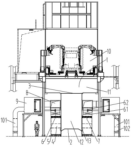
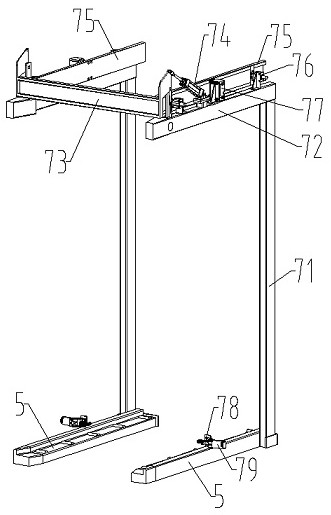
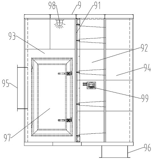
[0033] see Figure 1-4 , a large carton paint mist treatment system, located below the paint spray booth 10, including a T-shaped air guide chamber 1, the top of the T-shaped air guide chamber 1 communicates with the paint spray booth 10 through an air inlet, and the Both sides below the T-shaped air diversion chamber 1 are respectively provided with two groups of dry-type large carton groups, each group of dry-type large carton groups includes at least one dry-type large carton 4, and each dry-type large carton 4 is The clamping device 7 is used for fixed installation. The clamping device 7 is arranged on one side of the T-shaped air guiding chamber 1, and the side of the dry-type large paper box 4 close to the T-shaped air guiding chamber 1 passes through the air inlet. It communicates with the T-shaped air diversion chamber 1, and the top air outlet of each dry-type large paper box 4 is connected with an exhaust post-processing system through an upper exhaust pipe 8, and ea...


PUM


Abstract

The invention discloses a large paper box paint mist treatment system and a control method. The large paper box paint mist treatment system is arranged below a paint spraying chamber and comprises a T-shaped air flow guide chamber, the top of the T-shaped air flow guide chamber communicates with the paint spraying chamber through an air inlet, and the two sides of the lower portion of the T-shaped air flow guide chamber are each provided with two dry type large paper box sets; each large dry-type paper box set comprises at least one large dry-type paper box, each large dry-type paper box is fixedly installed through a clamping device, the side, close to the T-shaped air guide chamber, of each large dry-type paper box is communicated with the T-shaped air guide chamber through an air inlet, and a top exhaust outlet of each large dry-type paper box is communicated with an exhaust post-processing system through an upper exhaust pipe. An air volume distribution control system used for detecting the air speed in each upper exhaust pipe and controlling the air speed in each upper exhaust pipe to tend to be the same is arranged in each upper exhaust pipe, and by the adoption of the technical scheme, the whole structure is simple, the one-time investment is small, the consumption of consumables is low, and the service life is long.

Description

technical field [0001] The invention belongs to the technical field of paint mist treatment, and in particular relates to a large carton paint mist treatment system and a control method. Background technique [0002] At present, the spray booths that have been built and put into production can be divided into three types of paint mist treatment, namely, wet paint mist separation system, dry limestone paint mist separation system, and dry small carton paint mist separation system; among them, wet paint mist separation system The mist separation system has high energy consumption, high operating costs and three waste treatment costs; the dry limestone paint mist separation system has high one-time investment costs and high maintenance costs. [0003] The above-mentioned dry small carton paint mist separation system is widely used. For example, the patent number is: 201721301556.X, which discloses a carton dry paint mist treatment device that can replace the filter module onlin...

Claims


Application Information

Patent Timeline
Patent Type & Authority Applications(China)
IPC IPC(8): B01D46/00B01D46/02B01D46/42B01D46/44B05B14/43
CPCB01D46/0012B01D46/0039B01D46/023B01D46/4281B01D46/44B05B14/43
Inventor 张开旭毛维礼戴永超徐龙华台秀梅尹涛周瑞平
Owner MH ROBOT & AUTOMATION
Why Eureka
Try Eureka