
Special construction waste crusher

A technology of construction waste and crusher, which is applied in the direction of cleaning methods and utensils, smoke and dust removal, grain processing, etc., can solve the problems of sand entering the glasses, bad breathing, etc., and achieve the effect of reducing the impact

Inactive Publication Date: 2021-05-14
李志强
View PDF8 Cites 1 Cited by
  • Summary
  • Abstract
  • Description
  • Claims
  • Application Information

AI Technical Summary

Problems solved by technology

[0003] When the existing crusher crushes construction waste, the dust generated during the crushing will be released from the inlet, which will easily cause sand to enter the glasses of the staff feeding the material, and it is not good for breathing.

Method used


Image

  • Special construction waste crusher
  • Special construction waste crusher
  • Special construction waste crusher

Examples


Embodiment 1

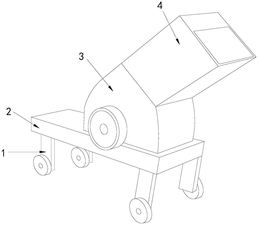
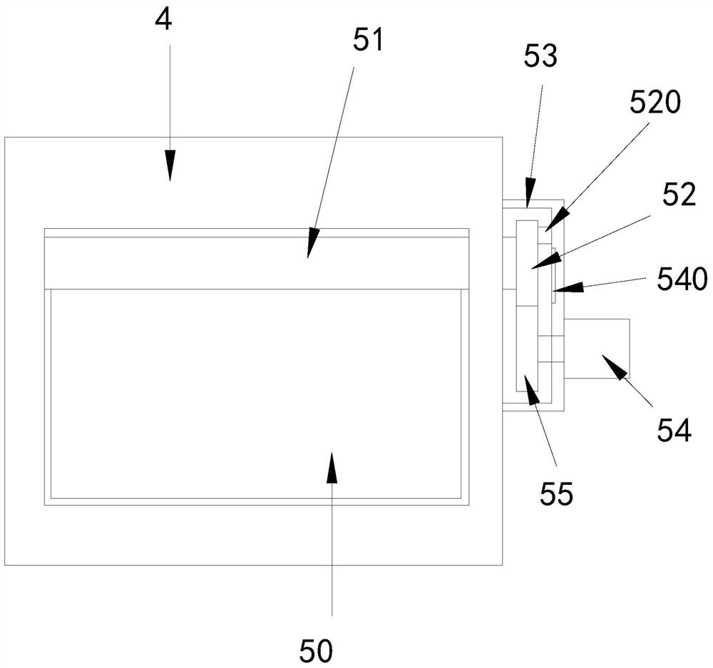
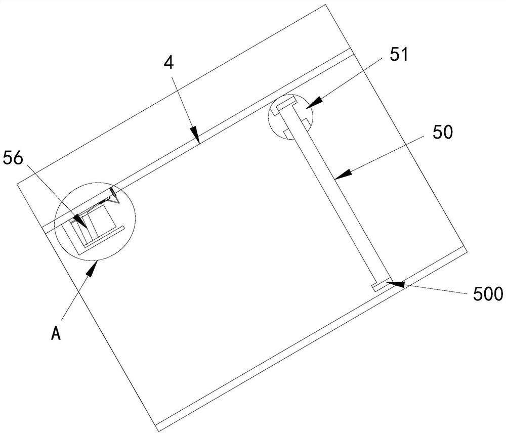
[0030] see Figure 1-6 , the present invention provides a special construction waste crusher technical solution: its structure includes a moving wheel 1, a base 2, a body 3, a feeding pipe 4, and a dust suppression device 5, the bottom of the base 2 is connected with a moving wheel 1, the The top of the base 2 is welded with an organic body 3, the top of the body 3 is connected with a feed pipe 4, and the feed pipe 4 is equipped with a dust suppression device 5, and the dust suppression device 5 includes a dust suppression plate 50, a rotating shaft 51, a rotating disk 52, Protective cover 53, motor 54, gear 55, electromagnetic structure 56, described rotating shaft 51 is installed in the feeding pipe 4, described rotating shaft 51 is provided with dust suppression board 50, described protective cover 53 is connected on the outside of feeding pipe 4 , the gear 55 is located in the protective cover 53 and is connected with the motor 54, a turntable 52 is arranged above the gear...

Embodiment 2

[0033] see Figure 1-6, the present invention provides a special construction waste crusher technical solution: its structure includes a moving wheel 1, a base 2, a body 3, a feeding pipe 4, and a dust suppression device 5, the bottom of the base 2 is connected with a moving wheel 1, the The top of the base 2 is welded with an organic body 3, the top of the body 3 is connected with a feed pipe 4, and the feed pipe 4 is equipped with a dust suppression device 5, and the dust suppression device 5 includes a dust suppression plate 50, a rotating shaft 51, a rotating disk 52, Protective cover 53, motor 54, gear 55, electromagnetic structure 56, described rotating shaft 51 is installed in the feeding pipe 4, described rotating shaft 51 is provided with dust suppression board 50, described protective cover 53 is connected on the outside of feeding pipe 4 , the gear 55 is located in the protective cover 53 and is connected with the motor 54, a turntable 52 is arranged above the gear ...


PUM


Abstract

The invention discloses a special construction waste crusher. The special construction waste crusher structurally comprises moving wheels, a base, a crusher body, a feeding pipe and a dust suppression device, wherein the moving wheels are connected to the bottom of the base, the crusher body is welded to the top of the base, the feeding pipe is connected to the top of the crusher body, and the dust suppression device is arranged on the feeding pipe, and comprises a dust suppression plate, a rotating shaft, a rotating disc, a protective cover, a motor, a gear and an electromagnetic structure; the rotating shaft is arranged in the feeding pipe; the dust suppression plate is arranged on the rotating shaft; the protective cover is connected to the outer side of the feeding pipe; the gear is arranged in the protective cover and connected with the motor; and the rotating disc is arranged above the gear. The special construction waste crusher has the beneficial effects that the dust suppression device is started by using the power of garbage entering, the dust suppression device can be raised to block a feeding pipe orifice again, garbage can enter smoothly, the dust suppression plate can be automatically reset for shielding, dust generated during crushing is prevented from flying out of the feeding pipe, and the influence on workers is reduced.

Description

technical field [0001] The invention relates to the construction field, in particular to a special crusher for construction waste. Background technique [0002] Concrete blocks and masonry after house dismantling, which cannot be directly put into secondary use, are regarded as construction waste. This kind of construction waste cannot be used directly, and discarding is a waste of resources. Therefore, people smash and rebuild these abandoned masonry. In order to be put into secondary use, the waste of resources and the pollution of the environment can be reduced. [0003] When the existing crusher crushes the construction waste, the dust generated during the crushing will be released from the inlet, which will easily cause sand to enter the glasses of the staff who feed the material, and it is not good for breathing. Contents of the invention [0004] The main purpose of the present invention is to overcome the deficiencies of the prior art and provide a special crusher...

Claims


Application Information

Patent Timeline
Patent Type & Authority Applications(China)
IPC IPC(8): B02C23/00B08B15/04B08B13/00
CPCB02C23/00B08B15/04B08B13/00
Inventor 刘燕清
Owner 李志强
Learn More