Lead-acid storage battery cast-weld production line

A lead-acid battery, battery technology, applied in lead-acid battery, lead-acid battery construction, foundry workshop and other directions, can solve the problems of poor coordination, relying on labor for feeding materials, low production efficiency, etc. Good efficiency, stability and uniformity

Active Publication Date: 2021-05-14
长兴金润科技有限公司
View PDF14 Cites 0 Cited by
  • Summary
  • Abstract
  • Description
  • Claims
  • Application Information

AI Technical Summary

Problems solved by technology

[0006] In view of the above problems, the present invention provides a lead-acid storage battery casting and welding production line, by setting the feeding conveying system and the casting and welding production system distributed by multiple groups corresponding to the feeding conveying system, and setting multiple groups and casting and welding production systems in the casting and welding production system The lead-immersed unit and the casting and welding mold corresponding to the welding unit are automatically transferred and distributed by the feeding conveying system to each casting and welding production system, and then multiple sets of casting and welding molds are alternately cooperated with the casting and welding unit to carry out the casting and welding operation, so that Realize the simultaneous operation of multiple sets of casting and welding production systems under one production line, and the close cooperation of each process structure in each group of casting and welding production systems to complete continuous casting and welding, which solves the existing problems in the prior art that rely on manual feeding, feeding and casting and welding Technical problems of poor operation coordination and low production efficiency

Method used


Image

  • Lead-acid storage battery cast-weld production line
  • Lead-acid storage battery cast-weld production line
  • Lead-acid storage battery cast-weld production line

Examples


Embodiment 1

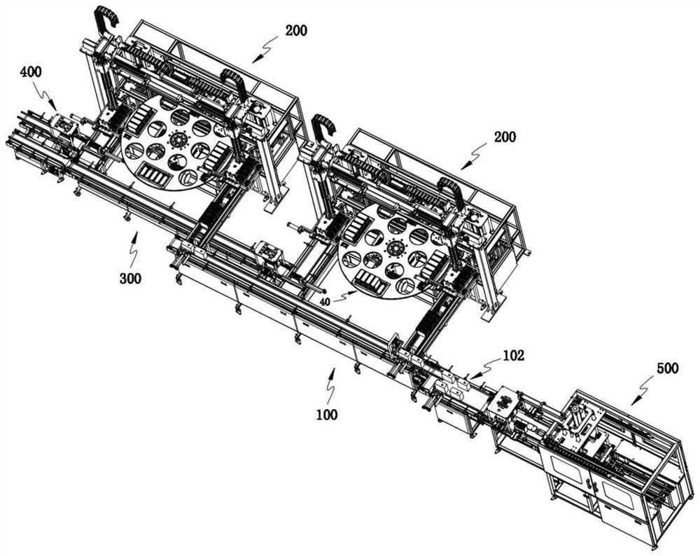
[0056] Such as figure 1 As shown, a lead-acid battery casting and welding production line includes a feed conveying system 100 and at least one group of casting and welding production systems 200 distributed along the conveying direction of the feed conveying system 100; during work, the feed conveying The system 100 distributes the storage batteries 102 in groups to each casting and welding production system 200 for casting and welding;

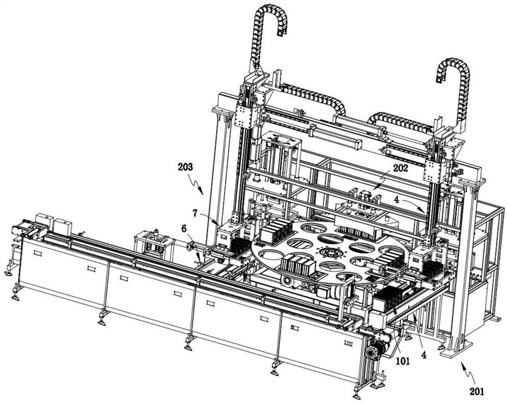
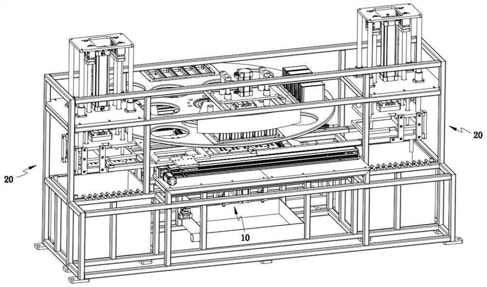
[0057] Such as Figure 2-3 As shown, the casting and welding production system 200 includes a casting and welding station 202, and the casting and welding station 202 is provided with a casting and welding unit 10, a plurality of sets of lead immersion units 20 arranged on the side of the casting and welding unit 10, and a plurality of sets of The casting mold 30 arranged in one-to-one correspondence with the lead immersion unit 20 and the transfer unit 50 that transfers the casting mold 30 between the casting unit 10 and each corresponding...

Embodiment 2

[0105] For the sake of brevity, only the difference between Embodiment 2 and Embodiment 1 is described below; the difference between Embodiment 2 and Embodiment 1 is:

[0106] Preferably, the rotating mechanism 11 is configured as a disc structure 111, and N bearing positions 12 for receiving the battery pack 101 are arranged equidistantly along the circumferential direction on the disc structure 111. The disc structure 111 per rotation

[0107] Preferably, N=4.

[0108] In this example, if figure 2 As shown, the disc structure 111 is equidistantly arranged with four bearing positions 12 along the circumferential direction. During operation, the disc structure 111 cooperates with the rhythm of casting and welding, and rotates 90° each time, so that three of the bearing positions 12 are respectively Correspondingly transfer to the loading station 201 , casting and welding station 202 and unloading station 203 .

[0109] In addition, in this embodiment, N can also be a nat...

Embodiment 3

[0111] For the sake of brevity, only the differences between Embodiment 3 and Embodiment 1 are described below; the differences between Embodiment 3 and Embodiment 1 are:

[0112] Preferably, the rotating mechanism 11 is configured as a cross structure 112, and one bearing position 12 is respectively provided on the four protruding ends 110 of the cross structure 112.

[0113] In this example, if Figure 17 As shown, each rotation of the cross structure 112 by 90° allows three of the carrying positions 12 to be transferred to the loading station 201 , casting and welding station 202 and unloading station 203 respectively.

[0114] work process:

[0115] The accumulators 102 that have completed the pole group pretreatment in the pole group pretreatment system 500 are arranged in two rows on the front-end conveying mechanism 8 for transmission, and are conveyed to the shunt conveying mechanism 9 one by one under the push of the first pushing component 81, With the cooperation ...


PUM


Abstract

The invention provides a lead-acid storage battery cast-weld production line. The lead-acid storage battery cast-weld production line comprises a feeding conveying system, at least one set of cast-weld production systems distributed in the conveying direction of the feeding conveying system, a discharging conveying system connected with the discharging ends of the cast-weld production systems, and a groove entering system arranged on a discharging path. The feeding conveying system and the multiple sets of cast-weld production systems distributed corresponding to the feeding conveying system are arranged, multiple sets of lead dipping units and cast-weld molds corresponding to cast-weld units are arranged in the cast-weld production systems, the feeding conveying system automatically conveys and distributes storage batteries to all the cast-weld production systems, then the multiple sets of cast-weld molds are alternately matched with the cast-weld units for cast-weld operation, and therefore the multiple sets of cast-weld production systems can work simultaneously under one production line, and all the procedure structures in all the sets of cast-weld production systems are in close fit to complete continuous cast-weld.

Description

technical field [0001] The invention relates to the technical field of lead-acid battery production, in particular to a lead-acid battery casting and welding production line. Background technique [0002] A lead-acid battery is a battery whose electrodes are mainly made of lead and its oxides, and the electrolyte is a sulfuric acid solution. In the production process of lead-acid batteries, in the production process of lead-acid batteries, several plates need to be welded together to form a single pole group according to the capacity design requirements of the battery, and then each single pole group is welded in series through poles , to form batteries of different voltages. [0003] The Chinese patent with the application number CN201920688806.2 discloses a battery automatic casting and welding machine, which opens a symmetrical feeding port on the top of the shell, cooperates with a sliding tray, and carries a group of batteries on the tray to move below the positioning ...

Claims


Application Information

Patent Timeline
IPC IPC(8): B22D19/04B22D25/04B22D27/04B22D47/00H01M10/14H01M10/12
CPCB22D19/04B22D25/04B22D27/04B22D47/00H01M10/14H01M10/12Y02P70/50
Inventor 吴建丰黄莉莉
Owner 长兴金润科技有限公司
Why Eureka
Try Eureka