Aerated concrete slab solid waste recovery system

An air-entrained concrete slab and recovery system technology, applied in the field of building material production, can solve problems such as slow production efficiency, easy flying of powder materials that affect the health of operators, and uneven foaming during the foaming process.

Active Publication Date: 2021-05-14
德阳优博络客新型建材有限公司
View PDF6 Cites 0 Cited by
  • Summary
  • Abstract
  • Description
  • Claims
  • Application Information

AI Technical Summary

Problems solved by technology

[0003] The manufacturer crushes the recycled aerated concrete waste, ball-mills it into powder, and gradually adds it to the mixing tank for mixing with normal materials. However, when the powder is added to the mixing tank, a large amount of powder mixes with the slurry to form a slurry-wrapped powder. The material will form air bubbles, which will make it difficult to stir out the air bubbles in the subsequent mixing process, and eventually lead to the technical problem of uneven foaming in the foaming process. If you need to add a small amount of powder, the production efficiency will be slow, and the site environment is poor. Powder is easy to fly out affect the operator's health

Method used


Image

  • Aerated concrete slab solid waste recovery system
  • Aerated concrete slab solid waste recovery system
  • Aerated concrete slab solid waste recovery system

Examples


Embodiment 1

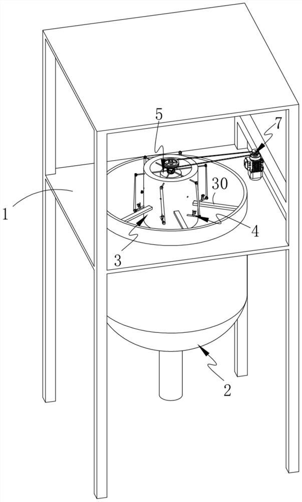
[0056] Such as Figure 1-5 As shown, an aerated concrete slab solid waste recovery system includes a mixing bin 2 arranged on an equipment platform 1, and is characterized in that it also includes a mixing bin 3 arranged in the mixing bin 2, passing through the mixing bin 2 The feeding system 4 on the side wall of the bin 3, the liquid spraying system 5 arranged inside the mixing bin 3, the defoaming system 6 arranged below the feeding system 4 and connected to the feeding system 4, and the liquid spraying system 5 connected drive system 7; the mixing bin 3 is fixed inside the top of the mixing bin 2 through several connecting rods 30

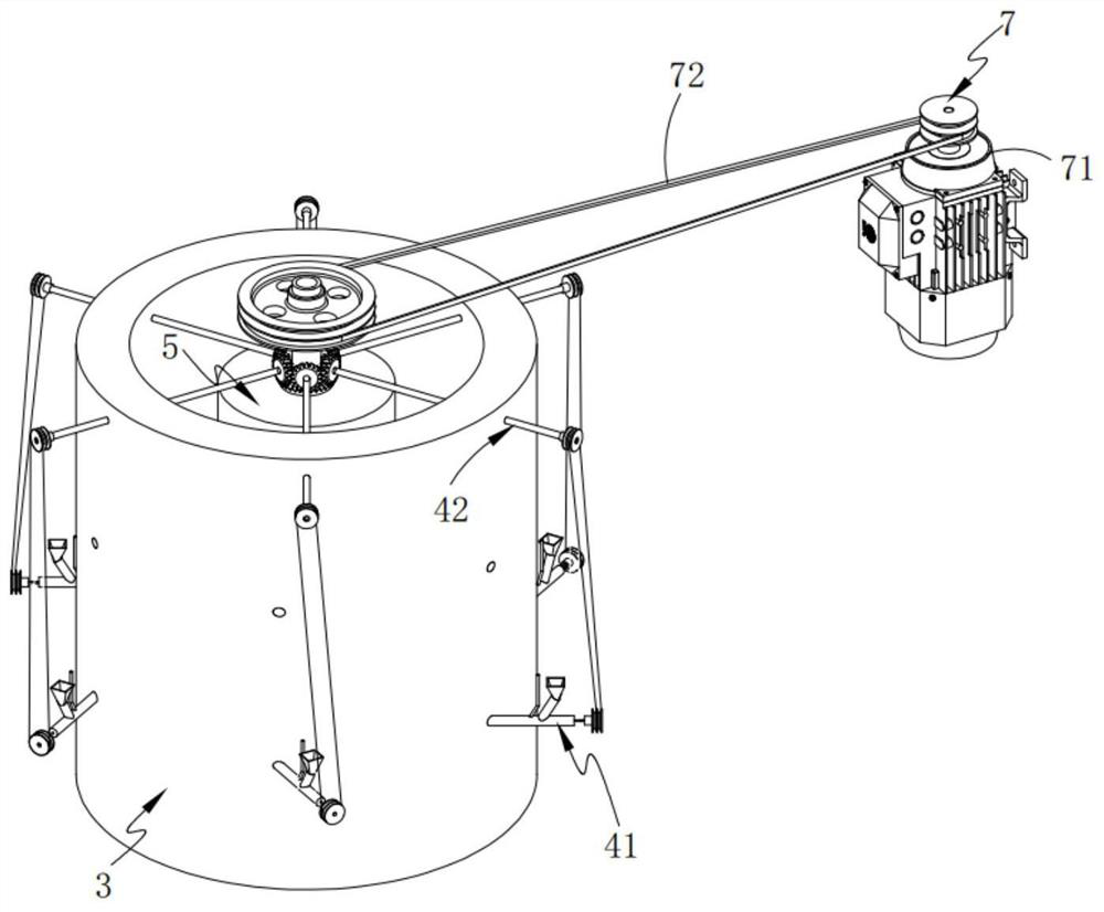
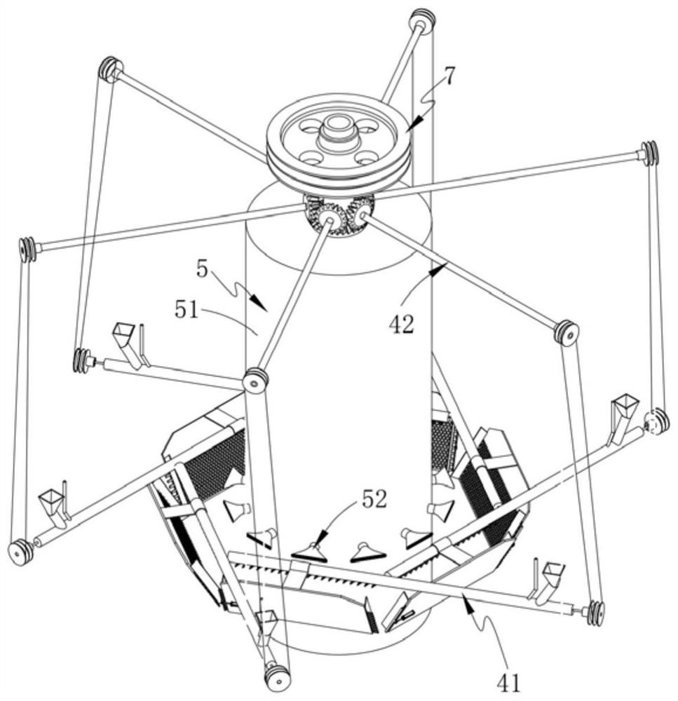
[0057] The feeding system 4 includes several groups of feeding units 41 uniformly distributed on the circumference and a feeding drive unit 42 that is connected to the several groups of feeding units 41 in one-to-one corresponding transmission;

[0058] The liquid spray system 5 includes a liquid storage bin 51 rotatably arranged in the mixing...

Embodiment 2

[0091] Such as Figure 14 As shown, the components that are the same as or corresponding to those in the first embodiment are marked with the corresponding reference numerals in the first embodiment. For the sake of simplicity, only the differences from the first embodiment will be described below. The difference between this embodiment two and embodiment one is:

[0092] In this embodiment, the feeding system 4 and the corresponding liquid spraying units 52 can be evenly distributed in multiple groups along the vertical direction, wherein the feeding drive unit 42 controls multiple groups of feeding systems 4 at the same time to realize synchronous feeding, and multiple groups are produced simultaneously. Thereby improving production efficiency.


PUM


Abstract

The invention provides an aerated concrete slab solid waste recovery system which comprises a stirring bin arranged on an equipment platform, a mixing bin arranged in the stirring bin, a feeding system penetrating through the side wall of the mixing bin, a liquid spraying system arranged in the mixing bin, a defoaming system arranged below the feeding system and connected with the feeding system, and a driving system connected with the liquid spraying system. Powder is sprayed into the mixing bin through the feeding system, liquid in a liquid storage bin is centrifugally sprayed out to form fog drops through cooperation of the liquid spraying system and the driving system, and the powder and the fog drops which move relatively collide with each other, so that the powder is mixed in the air; slurry drops falling onto a material receiving plate are subjected to secondary shearing and crushing through the defoaming system, so that bubbles in the slurry drops are completely removed, the powder and the liquid are mixed more uniformly, the subsequent stirring time is shortened, and the production efficiency is improved; and through continuous powder adding and continuous slurry spraying, continuous automatic production is achieved.

Description

technical field [0001] The invention relates to the technical field of building material production, in particular to an aerated concrete slab solid waste recycling system. Background technique [0002] Aerated concrete will produce a lot of waste after production and use and during the production process. How to deal with aerated concrete waste has become a key technical problem for various enterprises. Realizing the utilization of aerated concrete waste and turning waste into treasure is in line with today's Green cycle development concept. [0003] The manufacturer crushes the recycled aerated concrete waste, ball-mills it into powder, and gradually adds it to the mixing tank for mixing with normal materials. However, when the powder is added to the mixing tank, a large amount of powder mixes with the slurry to form a slurry-wrapped powder. The material will form air bubbles, which will make it difficult to stir out the air bubbles in the subsequent mixing process, and e...

Claims


Application Information

Patent Timeline
Patent Type & Authority Applications(China)
IPC IPC(8): B28C5/08B28C5/16B28C7/12
CPCB28C5/16B28C5/0806B28C7/128Y02W30/91
Inventor 杨哲峰彭文唐明
Owner 德阳优博络客新型建材有限公司
Why Eureka
Try Eureka