
Cleaning mechanism and cleaning device

A cleaning mechanism and cleaning water technology, applied in printing machines, general parts of printing machinery, printing, etc., can solve problems such as deformation of the spray rod, unequal distance from the spray hole to the cleaning cloth roll, inconsistent water volume and water pressure, etc. Achieve the effect of maintaining constant distance, uniform cleaning water and uniform water volume

Pending Publication Date: 2021-05-14
北京瑞奎德工业技术有限公司
View PDF0 Cites 0 Cited by
  • Summary
  • Abstract
  • Description
  • Claims
  • Application Information

AI Technical Summary

Problems solved by technology

[0008] One of the purposes of the present invention is to propose a cleaning mechanism and cleaning device, which solves the problem that the spray rod in the prior art is prone to deformation, resulting in unequal distances from the spray hole to the cloth roll for cleaning, and the problem of spraying from each spray hole on the spray rod. Technical problem of inconsistent water volume and water pressure

Method used


Image

  • Cleaning mechanism and cleaning device
  • Cleaning mechanism and cleaning device
  • Cleaning mechanism and cleaning device

Examples


Embodiment 1

[0042] This embodiment describes the cleaning mechanism of the present invention in detail.

[0043] The cleaning mechanism of this embodiment comprises a water pipe assembly, a water spray assembly and a cloth roll 3 for cleaning, such as Figure 7 or 8. Among them, the water pipe assembly is used for the circulation of cleaning water. There are multiple groups of water spray assemblies arranged in series on the water pipe assembly. keep constant. Preferably, the water spray assembly includes a solenoid valve 21 and a shower head 22, the solenoid valve 21 and the shower head 22 are connected in series, the solenoid valve 21 is used to control the working state of the shower head 22, and the shower head 22 has at least a water spray state or a non-water spray state, such as Figure 7 or 8.

[0044] In the cleaning mechanism of this embodiment, the water pipe assembly is used for the circulation of cleaning water, and multiple groups of water spray assemblies are arranged in...

Embodiment 2

[0060] This embodiment describes the cleaning device of the present invention in detail.

[0061] The cleaning device of this embodiment includes the cleaning mechanism of any technical solution in Embodiment 1, such as Figure 7shown. The cleaning device of this embodiment has the cleaning mechanism of any one of the technical solutions in Embodiment 1, so that the cleaning device of this embodiment has the ability to keep the distance between the water spray assembly and the cleaning cloth roll 3 constant, each water spray assembly The sprayed cleaning water has the advantages of uniform water volume and constant water pressure. That is, the cleaning device of this embodiment solves the problem that the spray rod 1' is easily deformed in the prior art, resulting in the unequal distance from the spray hole 101' to the cleaning cloth roll 3, and the spraying holes 101' on the spray rod 1'. The technical problem of inconsistent water volume and water pressure.

[0062] When ...


PUM


Abstract

The invention discloses a cleaning mechanism and a cleaning device, and relates to the technical field of printing. The technical problems that in the prior art, a spraying rod is prone to deform, so that the distances between spraying holes and a cloth roll for cleaning are unequal; and the water quantity and water pressure of water sprayed out of the spraying holes in the spraying rod are inconsistent are solved. The cleaning mechanism comprises a water pipe assembly, water spraying assemblies and a cloth roll for cleaning, wherein the water pipe assembly is used for cleaning water to circulate, the water pipe assembly is provided with the plurality of water spraying assemblies in series, the water spraying assemblies are independently fixed to a bottom plate, and the distance between each water spraying assembly and the cloth roll for cleaning is kept constant; and the water spraying assemblies comprise electromagnetic valves and nozzles, wherein the electromagnetic valves and the nozzles are connected in series, the electromagnetic valves are used for controlling the working states of the nozzles, and the nozzles at least have water spraying states or non-water-spraying states. According to the cleaning mechanism and the cleaning device, the distances between the water spraying assemblies and the cloth roll for cleaning can be kept constant, the water quantity of cleaning water sprayed by the water spraying assemblies is uniform, and the water pressure is constant.

Description

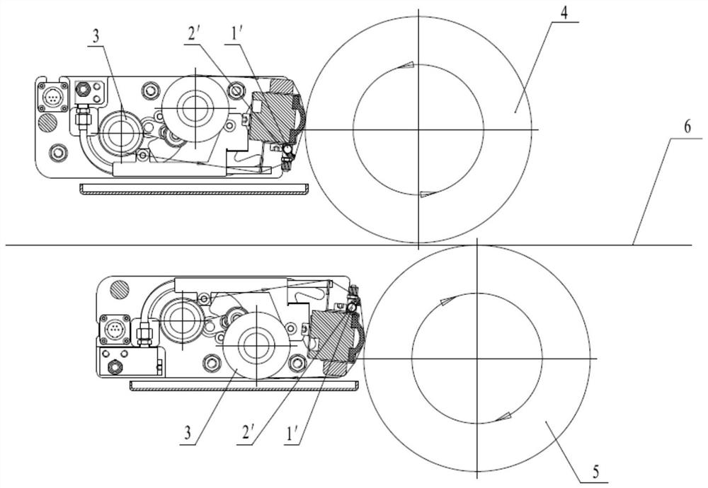
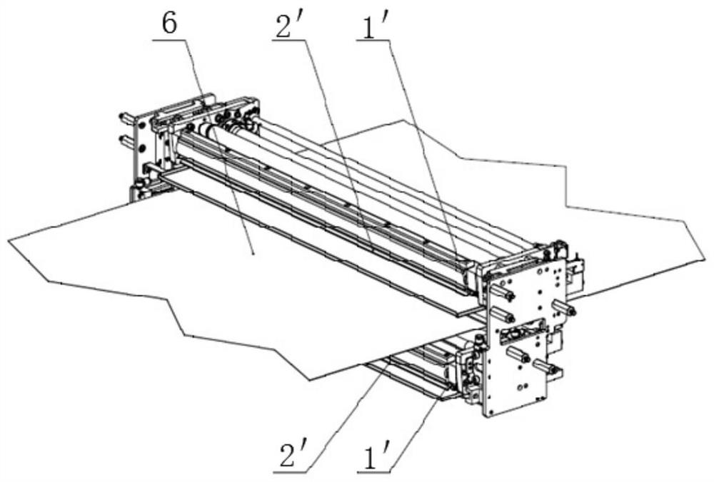
technical field [0001] The invention relates to the technical field of printing, in particular to a cleaning mechanism for cleaning printing press cylinders and a cleaning device comprising the cleaning mechanism. Background technique [0002] During the printing process of the web printing machine, a large amount of ink and paper dust will remain on the surface of the upper rubber cylinder and the lower rubber cylinder, which need to be cleaned from time to time. In the prior art, there are usually two ways to clean the rubber cylinder: the first is manual cleaning; the second is the automatic cleaning of the spray rod type. [0003] Manual cleaning needs to disconnect the printing paper between the upper rubber cylinder and the lower rubber cylinder before manual wiping. The manual cleaning method not only consumes a lot of manpower, but also takes a lot of time to reload the disconnected paper into the printing machine, which affects printing efficiency. figure 1 with ...

Claims


Application Information

Patent Timeline
Patent Type & Authority Applications(China)
IPC IPC(8): B41F35/02
CPCB41F35/02
Inventor 宋常红苏云香
Owner 北京瑞奎德工业技术有限公司
Learn More