Sewage filtering and impurity removing device

A technology for filtering impurities and sewage, which is applied in the direction of filtration treatment, water/sewage treatment, grease/oily substance/floating matter removal device, etc. question

Inactive Publication Date: 2021-05-14
仇庆东
View PDF1 Cites 1 Cited by
  • Summary
  • Abstract
  • Description
  • Claims
  • Application Information

AI Technical Summary

Problems solved by technology

[0006] Aiming at the deficiencies of the prior art, the present invention provides a sewage filtering and impurity removal device, which solves the problem that the traditional sewage treatment equipment can only filter and separate the particulate impurities in the sewage, but cannot filter the grease on the surface of the oily sewage, and the grease will block the sewage Contact with purification substances affects the subsequent treatment effect of sewage, and the existing equipment has low efficiency in filtering grease

Method used


Image

  • Sewage filtering and impurity removing device
  • Sewage filtering and impurity removing device
  • Sewage filtering and impurity removing device

Examples


Embodiment 1

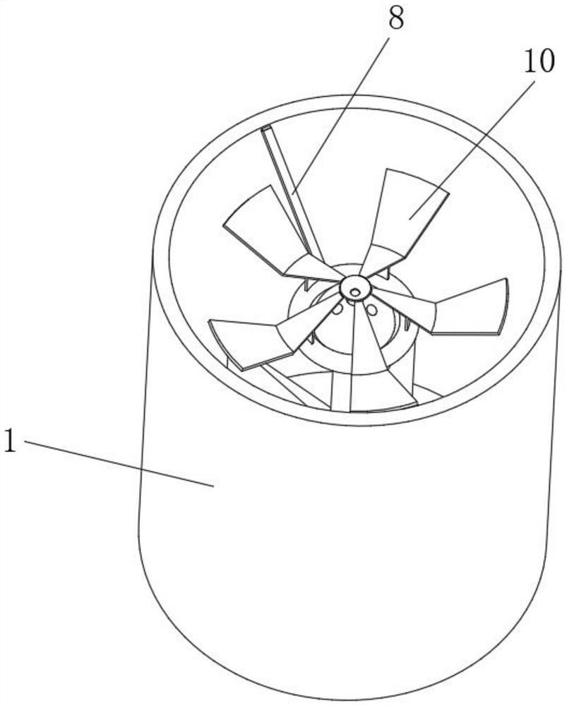
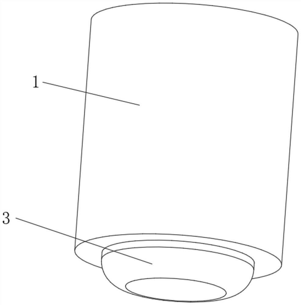
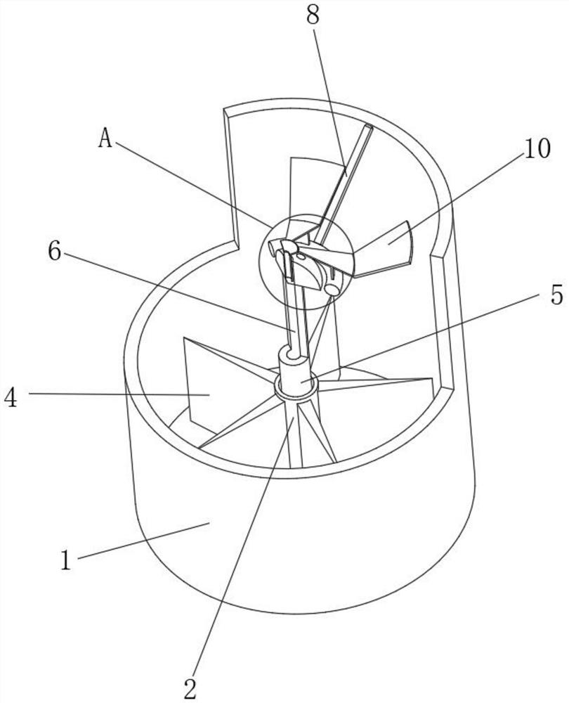
[0034] Such as Figure 1-4As shown, the present invention provides a technical solution: a sewage filtering and impurity removal device, including a filtering treatment barrel 1, the middle position of the inner bottom of the filtering treatment barrel 1 is rotatably connected with a drive insertion shaft 2, and the middle of the outer bottom of the filtering treatment barrel 1 The location is fixed and connected with a recovery groove 3, and the periphery of the outer surface of the driving insertion shaft 2 is uniformly and fixedly connected with a driving fan 4, and the inside of the top of the driving insertion shaft 2 is penetrated and slidably connected with a transmission insertion rod 5, and the bottom of the driving insertion shaft 2 is connected to the recovery slot. The interior of the groove 3 is connected, and the middle position inside the transmission insertion rod 5 is provided with a liquid guide inner tube 6. The top of the transmission insertion rod 5 away fr...

Embodiment 2

[0038] Such as Figure 5 As shown, on the basis of Embodiment 1, the present invention provides a technical solution: a sewage filter and impurity removal device, the guide swing mechanism 10 includes a filter diverter plate 101, one end of the bottom of the filter diverter plate 101 and the floating carrier plate 9 Fixedly connected, the right side of the bottom end of the filter diverter plate 101 is rotatably connected with a contact separation plate 102 , and the inside of the contact separation plate 102 is uniformly provided with a buffer chute 103 .

[0039] A buffer inner groove 104 is uniformly arranged on the surface of the top of the filter splitter plate 101, a sealing cone groove 105 is fixedly connected to the position close to the left side of the separation plate 102, and a sealing plug piece 106 runs through and is slidably connected to the inside of the sealing cone groove 105. Avoid collisions to produce intense water splashes that affect the filtration and ...

Embodiment 3

[0043] Such as Figure 6 As shown, on the basis of Embodiment 1 and Embodiment 2, the present invention provides a technical solution: a sewage filter and impurity removal device, the directional restriction assembly 109 includes a restriction baffle a1, a restriction baffle a1 and a filter diverter plate 101 Fixedly connected, one side of the limiting baffle a1 is fixedly connected with a guide buffer plate a2.

[0044] The inner surface of the guide buffer plate a2 is provided with a directional guide groove a3, and the top output end of the directional guide groove a3 is arranged correspondingly to the guide bucket groove 13. The purpose of avoiding the diversion of grease liquid to the outside and improving the efficiency of grease filtration and separation.


PUM


Abstract

The invention discloses a sewage filtering and impurity removing device. The device comprises a filtering treatment barrel, a driving insertion shaft is rotationally connected to the middle position of the bottom end in the filtering treatment barrel, a recycling groove is fixedly connected to the middle position of the bottom end outside the filtering treatment barrel, driving fan blades are uniformly and fixedly connected to the periphery of the outer surface of the driving insertion shaft, a transmission insertion rod penetrates through the interior of the top end of the driving insertion shaft and is slidably connected with the interior of the top end of the driving insertion shaft, the bottom of the driving insertion shaft communicates with the interior of the recovery tank, a liquid guide inner pipe is arranged in the middle of the interior of the transmission insertion rod, a floating convex head is fixedly connected to the top of the end, away from the driving insertion shaft, of the transmission insertion rod,the top of the filtering treatment barrel is rotated and connected with an auxiliary connecting rod, the end, away from the filtering treatment barrel, of the auxiliary connecting rod is rotationally connected with a floating carrier plate, and the top of the floating carrier plate is fixedly connected with a material guiding and swinging mechanism. According to the sewage filtering and impurity removing device, part of grease accumulated in the center position is filtered through the centrifugal force of rotation.

Description

technical field [0001] The invention relates to the technical field of filtration and impurity removal, in particular to a sewage filtration and impurity removal device. Background technique [0002] Sewage treatment is the process of purifying sewage to meet the water quality requirements for discharge into a certain water body or reuse. [0003] For example, the Chinese invention publication number is: CN107386420A, a kind of debris removal device used in sewage filtration, including pipelines and filter screens, a driving motor is installed on the left side of the pipeline, and a rotating shaft is installed on the left end of the driving motor , the driving wheel is installed on the rotating shaft, the rotating shaft passes through the side wall of the pipe and the end is equipped with a first helical gear, the fixed rod is installed between the described pipes, and the middle position of the fixed rod is set The first bearing, the first threaded rod is pierced in the fi...

Claims


Application Information

Patent Timeline
Patent Type & Authority Applications(China)
IPC IPC(8): C02F9/02
CPCC02F1/001C02F1/38C02F1/40C02F9/00C02F2201/002C02F2201/004C02F2303/14
Inventor 房凌
Owner 仇庆东
Why Eureka
Try Eureka