Melt control in-situ synthesized aluminum-based composite material preparation method with continuous treatment function

An aluminum-based composite material, in-situ self-generated technology, applied in the field of aluminum-based composite materials, can solve the problems of high-temperature oxidation resistance, etc., and achieve the effects of improving life, saving process preparation time and energy consumption, and uniform distribution

Active Publication Date: 2021-05-14
ALUMICS MATERIALS INST SHANGHAI JIAO TONG UNIV (ANHUI HUAIBEI) +1
View PDF11 Cites 1 Cited by
  • Summary
  • Abstract
  • Description
  • Claims
  • Application Information

AI Technical Summary

Problems solved by technology

[0005] At present, most of the aluminum melt degassing rotors are made of graphite material, because graphite material has excellent thermal shock resistance and can be machined, and aluminum liquid does not infiltrate graphite, but the weakness of graphite material is that it is not resistant to high temperature oxidation, resulting in long service life. Only need to replace in 14-20 days

Method used


Image

  • Melt control in-situ synthesized aluminum-based composite material preparation method with continuous treatment function
  • Melt control in-situ synthesized aluminum-based composite material preparation method with continuous treatment function
  • Melt control in-situ synthesized aluminum-based composite material preparation method with continuous treatment function

Examples


Embodiment 1

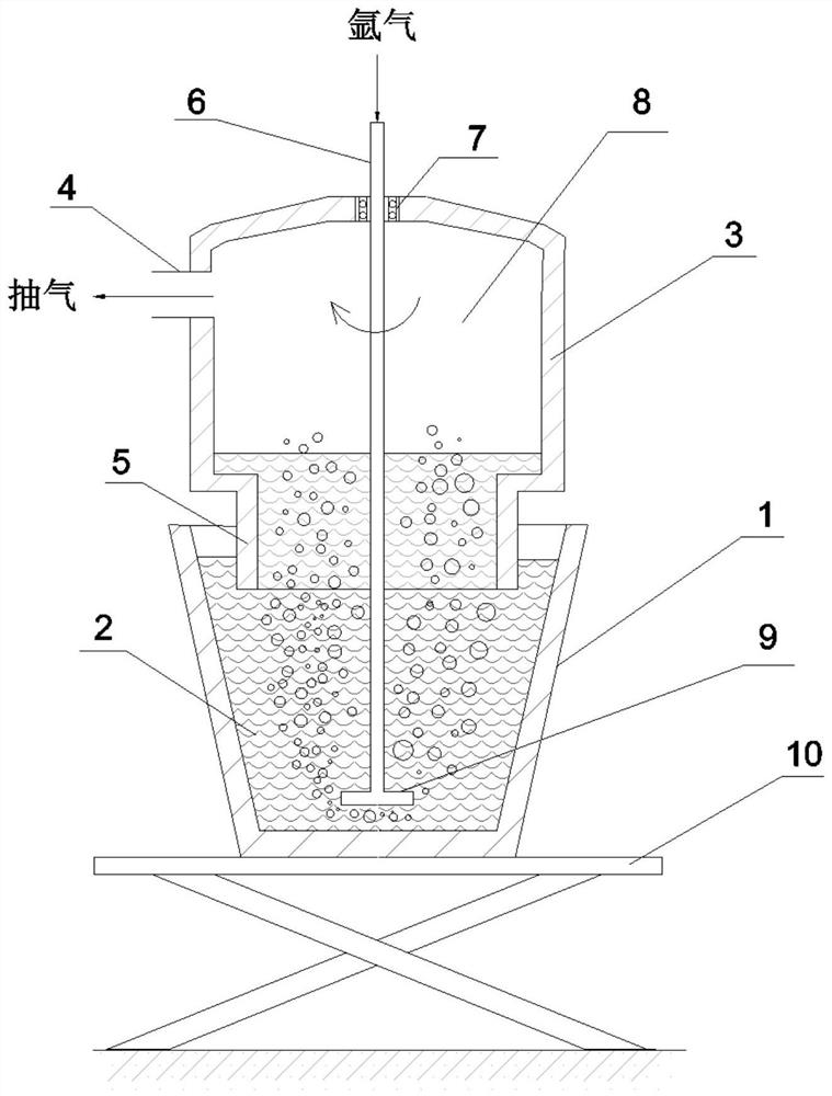
[0039] Such as figure 1 As shown, the pure aluminum or aluminum alloy substrate is melted at 700-760° C., the aluminum melting furnace 1 containing the aluminum melt 2 is placed on the hydraulic lifting table 10, and reaction salts and reaction aids are added for reaction. The hydraulic lifting table 10 is raised so that the dip tube 5 of the vacuum bag 3 arranged above the aluminum melting furnace 1 is immersed into the aluminum melt 2 . The vacuum chamber 8 of the vacuum bag 3 is evacuated through the pumping port 4, so that the aluminum melt 2 enters the vacuum bag 3 under atmospheric pressure.

[0040] At the same time, the aluminum melt is sprayed with argon rotation: the graphite rotor is lowered, and the rotating rod 6 of the graphite rotor passes through the sealed bearing 7 arranged on the top of the vacuum bag 3, passes through the vacuum chamber 8, and inserts the nozzle 9 into the bottom of the aluminum melt 2. At the bottom, argon gas is blown in through the midd...

Embodiment 2

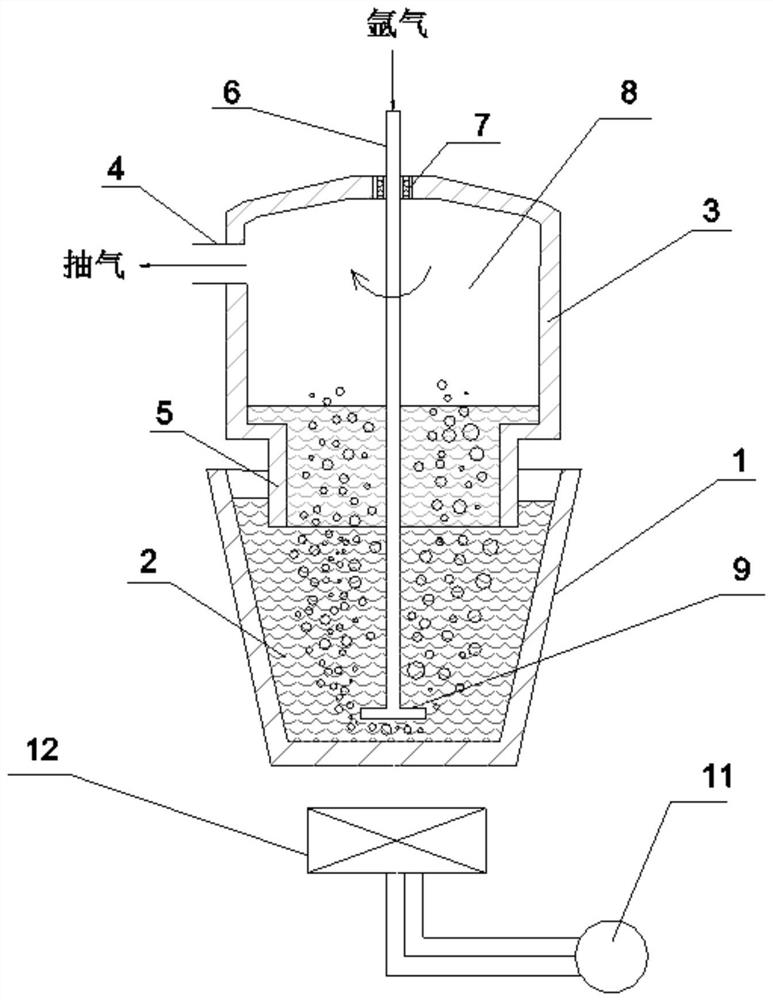
[0049] Such as figure 2 As shown, the pure aluminum or aluminum alloy substrate is melted at 700-760°C, the aluminum melt 2 is placed in the aluminum melting furnace 1, and reaction salts and reaction aids are added for reaction. The immersion tube 5 of the vacuum bag 3 arranged above the aluminum melting furnace 1 is immersed into the aluminum melt 2 . The vacuum chamber 8 of the vacuum bag 3 is evacuated through the pumping port 4, so that the aluminum melt 2 enters the vacuum bag 3 under atmospheric pressure.

[0050] At the same time, the aluminum melt is sprayed with argon rotation: the graphite rotor is lowered, and the rotating rod 6 of the graphite rotor passes through the sealed bearing 7 arranged on the top of the vacuum bag 3, passes through the vacuum chamber 8, and inserts the nozzle 9 into the bottom of the aluminum melt 2. At the bottom, argon gas is blown in through the middle hole of the rotating rod 6 and ejected from the rotating nozzle 9. The formed bubbl...

Embodiment 3

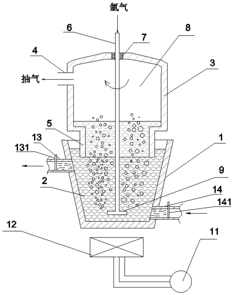
[0060] Such as image 3 As shown, the pure aluminum or aluminum alloy substrate is melted at 700-760°C, the aluminum melt 2 is placed in the aluminum melting furnace 1, and reaction salts and reaction aids are added for reaction. The immersion tube 5 of the vacuum bag 3 arranged above the aluminum melting furnace 1 is immersed into the aluminum melt 2 . The vacuum chamber 8 of the vacuum bag 3 is evacuated through the pumping port 4, so that the aluminum melt 2 enters the vacuum bag 3 under atmospheric pressure.

[0061] At the same time, the aluminum melt is sprayed with argon rotation: the graphite rotor is lowered, and the rotating rod 6 of the graphite rotor passes through the sealed bearing 7 arranged on the top of the vacuum bag 3, passes through the vacuum chamber 8, and inserts the nozzle 9 into the bottom of the aluminum melt 2. At the bottom, argon gas is blown in through the middle hole of the rotating rod 6 and ejected from the rotating nozzle 9. The formed bubble...


PUM


Abstract

The invention discloses a melt control in-situ synthesized aluminum-based composite material preparation method with a continuous treatment function. The melt control in-situ synthesized aluminum-based composite material preparation method with the continuous treatment function comprises the following steps of: providing a vacuum bag, which comprises an extraction opening and an immersion pipe; providing an electromagnetic stirring device, wherein the electromagnetic stirring device is arranged below an aluminum smelting furnace; arranging an aluminum melt outlet runner on the side wall of the upper part of a furnace body of the aluminum smelting furnace; arranging an aluminum melt inlet runner on the side wall of the bottom of the furnace body of the aluminum smelting furnace; respectively arranging flow stopping sliding plates on the aluminum melt outlet runner and the aluminum melt inlet runner; after pure aluminum or an aluminum alloy matrix in the aluminum smelting furnace is smelted, adding reaction salt and a reaction auxiliary agent for reaction; immersing the immersion pipe of the vacuum bag into the aluminum melt, and vacuumizing a vacuum chamber through the extraction opening; lowering a graphite rotor, so that a rotating rod penetrates through a vacuum chamber of the vacuum bag through a sealing bearing arranged at the top of the vacuum bag; and inserting a spray head into the bottom of the aluminum melt for argon rotary injection.

Description

technical field [0001] The invention relates to aluminum-based composite materials, in particular to the preparation of in-situ self-generated aluminum-based composite materials. Background technique [0002] The in-situ self-generated aluminum matrix composite material is to use the chemical reaction between different elements or chemicals under certain conditions to generate one or several ceramic phase particles in the aluminum matrix to achieve the purpose of improving the performance of a single metal alloy. The composite material prepared by in-situ self-generation has no pollution on the surface of the reinforcement, and the compatibility between the matrix and the reinforcement is good. By selecting the reaction type and controlling the reaction parameters, different types and quantities of in-situ reinforced particles can be obtained. [0003] However, the in-situ self-generated aluminum matrix composites have high requirements on the conditions including degassing...

Claims


Application Information

Patent Timeline
IPC IPC(8): C22C1/10C22C1/06C22C21/00C22B9/04C22B9/05C22B9/10C22B21/06
CPCC22B9/04C22B9/05C22B9/10C22B21/068C22C1/06C22C1/1036C22C21/00
Inventor 王浩伟王建中李爱平
Owner ALUMICS MATERIALS INST SHANGHAI JIAO TONG UNIV (ANHUI HUAIBEI)
Why Eureka
Try Eureka