Immersed tunnel concrete pouring system and method

An immersed tube tunnel and concrete technology, which is applied in the field of concrete pouring, can solve the problems of long pouring tubes and the inability to meet the pouring requirements of self-compacting steel shell concrete immersed tubes.

Pending Publication Date: 2021-05-14
CCCC FOURTH HARBOR ENG CO LTD
View PDF5 Cites 2 Cited by
  • Summary
  • Abstract
  • Description
  • Claims
  • Application Information

AI Technical Summary

Problems solved by technology

[0003] The purpose of the present invention is to aim at the existing concrete pouring method in the prior art, which has the disadvantages of random arrangement of pump pipes and long pouring pipes, and can no longer meet the pouring requirements of self-compacting steel shell concrete immersed pipes, and provides Concrete pouring system and method for immersed tube tunnel

Method used


Image

  • Immersed tunnel concrete pouring system and method
  • Immersed tunnel concrete pouring system and method
  • Immersed tunnel concrete pouring system and method

Examples


Embodiment 1

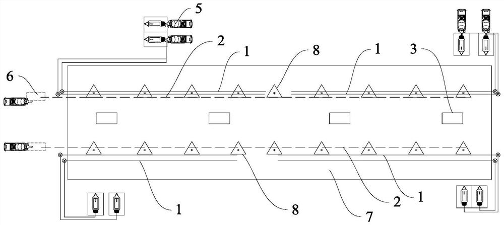
[0039] Such as figure 1 As shown, a concrete pouring system for an immersed tube tunnel includes a pouring pipe 1 , a return pipe 2 , a pouring machine 3 and an elbow 4 .

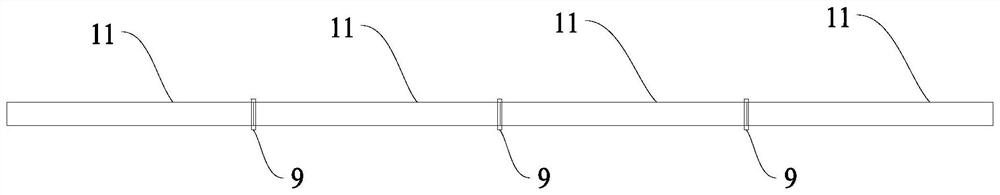
[0040] A plurality of pouring pipes 1 are symmetrically arranged in the prefabricated site 7, and each said pouring pipe 1 is arranged from the end of the prefabricated site to the center, such as figure 2 As shown, each pouring pipe 1 includes a plurality of pouring pipe segments 11, the length of the pouring pipe segments 11 is 2m-5m, and the interface between two adjacent pouring pipe segments 11 is through a pump pipe joint 9 detachable connections. The pouring pipe 1 is a high-pressure steel pipe, and a hose can be used locally.

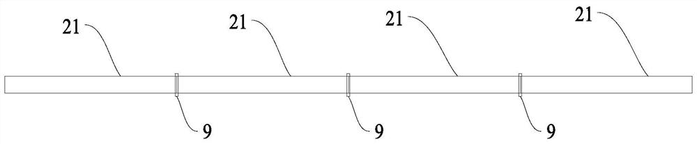
[0041] A plurality of return pipes 2 are symmetrically arranged in the prefabricated site 7, and each said return pipe 2 is arranged from one end of the prefabricated site to the other end, as image 3 As shown, each of the return pipes 2 includes a plurality of return pi...

Embodiment 2

[0046] Such as Figure 1-Figure 5 Shown, a kind of immersed tube tunnel concrete pouring method comprises the following steps:

[0047] Step 1: arranging the concrete pouring system of the immersed tube tunnel as described in embodiment 1 in the prefabricated site;

[0048] Step 2: move the pouring machine 3 to the position 8 to be poured, and connect the feed inlet 31 to the interface of the nearest pouring pipe segment 11 through the elbow 4;

[0049] Step 3: Self-compacting concrete enters the pouring pipe 1 from the drag pump 5, enters the pouring machine 3 through the feed port 31, and pours concrete;

[0050] Step 4: After the concrete pouring is completed, the connection between the feed inlet 31 and the elbow 4 is removed;

[0051] Step 5: Connect the elbow 4 to the interface of the nearest return pipe segment 21 to form a cleaning channel, such as Figure 4 shown;

[0052] Step 6: Insert a sponge ball into the cleaning channel, pump water or air into the cleaning ...


PUM


Abstract

The invention discloses an immersed tunnel concrete pouring system and method. The pouring system comprises a pouring pipe, a backflow pipe, a pouring machine and a bent pipe, wherein the pouring pipe comprises a plurality of pouring pipe sections which are detachably connected, the backflow pipe comprises a plurality of backflow pipe sections which are detachably connected, the pouring machine can move and is provided with a feeding port, a connector of any pouring pipe section can be connected to the feeding port through the bent pipe, the connector of any pouring pipe section can be connected to a connector of any backflow pipe section through the bent pipe, the pouring method comprises the following steps that the pouring system is arranged in a prefabrication site, the pouring machine is moved to the to-be-poured position, the feeding port is connected to the connector of the nearest pouring pipe section through the bent pipe, self-compacting concrete enters the pouring machine through the pouring pipe, concrete pouring is carried out, after the concrete pouring is completed, connection between the feeding port and the bent pipes is removed, and the bent pipe is connected to the connector of the nearest return pipe section to form a cleaning channel for cleaning.

Description

technical field [0001] The invention relates to the technical field of concrete pouring, in particular to a concrete pouring system and method for an immersed tube tunnel. Background technique [0002] The steel shell immersed tube is an integrated structure. The prefabrication of immersed tube has strict requirements on concrete performance indicators. The longer the pouring tube is, the more unfavorable it is to the performance of self-compacting concrete. The space in the immersed tube prefabrication site is limited, and the existing concrete pouring method has the disadvantages of random arrangement of pump pipes and long pouring pipes, which can no longer meet the pouring requirements of self-compacting steel shell concrete immersed tubes. Contents of the invention [0003] The purpose of the present invention is to aim at the existing concrete pouring method in the prior art, which has the disadvantages of random arrangement of pump pipes and long pouring pipes, and ...

Claims


Application Information

Patent Timeline
Patent Type & Authority Applications(China)
IPC IPC(8): E21D11/10
CPCE21D11/105
Inventor 黄文慧毛维杰张文森嵇廷杨洋林伟才吴宇恒陈远邓军孙帅张青梁彦君邓懋新
Owner CCCC FOURTH HARBOR ENG CO LTD
Why Eureka
Try Eureka