Check patentability & draft patents in minutes with Patsnap Eureka AI!

Multi-stage controllable progressive energy-absorbing lattice structure

A lattice structure and endpoint technology, applied in special data processing applications, instruments, geometric CAD, etc., can solve the problems of inability to protect, reduce the initial strength and stiffness of energy-absorbing structures, and high loads of protected objects with initial strength and stiffness, and achieve The effect of strong stability

Pending Publication Date: 2021-05-14
INST OF MECHANICS - CHINESE ACAD OF SCI
View PDF0 Cites 5 Cited by
  • Summary
  • Abstract
  • Description
  • Claims
  • Application Information

AI Technical Summary

Problems solved by technology

In reality, energy-absorbing structures face various impact velocities and protected targets. However, the energy-absorbing strategy of CEA cannot provide effective protection for different impact velocities and different targets. More efficient energy-absorbing devices need It has better adaptability to different speeds and different protection targets, that is, it can completely suppress the damage caused by excessive peak load when a low-speed collision occurs, and absorb as much impact as possible at a higher collision speed Kinetic energy brought, minimize damage as much as possible
[0005] The higher initial strength and stiffness of the tension-compression dominant lattice structure makes the protected object prone to damage caused by excessive load at lower speeds
In order to improve the safety factor of the energy-absorbing device, it is necessary to reduce the initial strength and stiffness of the energy-absorbing structure as much as possible, and in the CEA energy-absorbing strategy, there is often a contradiction between lower initial peak load and higher energy absorption

Method used


Image

  • Multi-stage controllable progressive energy-absorbing lattice structure
  • Multi-stage controllable progressive energy-absorbing lattice structure
  • Multi-stage controllable progressive energy-absorbing lattice structure

Examples


Embodiment Construction

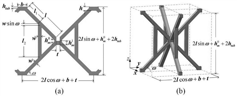
[0032] The specific structure and implementation process of this solution will be described in detail below through specific embodiments and accompanying drawings.

[0033] Such as figure 1 As shown, in one embodiment of the present invention, a multi-level controllable progressive energy-absorbing lattice structure is disclosed, including spliced ​​rods, and a unit cell structure and a lattice structure composed of spliced ​​rods.

[0034] The splicing rod includes two X-shaped orthogonally connected oblique rods, vertical rods connecting the two oblique rods are respectively arranged on the opposite sides in the horizontal direction of the connection point of the two oblique rods, and the connection positions of the two vertical rods correspond to each other and parallel to each other; that is, the vertical bars are only symmetrically arranged on opposite sides of the oblique bars, and the overall shape is a butterfly-shaped two-dimensional pattern.

[0035] The unit cell s...


PUM


Abstract

The invention provides a multi-stage controllable progressive energy-absorbing lattice structure which comprises: a splicing rod piece, whrein the splicing rod piece comprises two X-shaped orthogonally connected inclined rods, vertical rods connected with the two inclined rods are arranged on the two sides of the horizontal direction of the connecting point of the two inclined rods respectively, and the connecting positions of the two vertical rods correspond to each other and are parallel to each other; a unit cell structure which is formed by connecting points of two splicing rod pieces in an orthogonal interlocking assembly mode; a lattice structure which is formed by mutually connecting a plurality of unit cell structures on the plane through the end points of the adjacent inclined rods, wherein the interlocking positions of the unit cell structures are fixed through vacuum brazing. The mechanical property of multi-stage progressive energy absorption of a light structure is achieved through the lattice structure, and a multi-stage controllable butterfly-shaped lattice structure with a stress-strain curve gradually rising is provided according to configuration conversion in the lattice structure compression process.

Description

technical field [0001] The invention relates to the field of structural energy absorption, in particular to a multi-stage controllable progressive energy-absorbing lattice structure. Background technique [0002] The energy absorption of impact loads has a wide range of application requirements in many fields such as automobiles, helmets, and packaging, and it has always been the focus of research and application of traditional lightweight porous structures. In the design of energy-absorbing structures, usually the most ideal way of energy absorption is constant peak load constant absorbed energy (CEA). In lightweight porous structures, foam materials have always been regarded as ideal energy-absorbing materials. It is precisely because of the relatively stable yield platform in the loading process and its bending-dominant deformation characteristics that the foam materials have a low The initial stiffness and initial strength effectively reduce the damage to the protected ...

Claims


Application Information

Patent Timeline
IPC IPC(8): G06F30/17G16C60/00G06F111/10
CPCG06F30/17G16C60/00G06F2111/10
Inventor 刘文峰宋宏伟黄晨光
Owner INST OF MECHANICS - CHINESE ACAD OF SCI
Features
  • R&D
  • Intellectual Property
  • Life Sciences
  • Materials
  • Tech Scout
  • Unparalleled Data Quality
  • Higher Quality Content
  • 60% Fewer Hallucinations
Learn More