Assembly part relative pose estimation monitoring method based on deep learning

A technology of relative pose and deep learning, applied in computing, image analysis, image enhancement, etc., can solve problems such as occlusion of assembly parts, lack of overall correlation, failure to estimate the relative pose of assembly parts, etc.

Active Publication Date: 2021-05-14
QINGDAO TECHNOLOGICAL UNIVERSITY
View PDF5 Cites 4 Cited by
  • Summary
  • Abstract
  • Description
  • Claims
  • Application Information

AI Technical Summary

Problems solved by technology

However, most mechanical parts have no texture, no color, and reflective features, and there are serious occlusions in assembly parts, which bring challenges to the pose estimation of parts.
At present, the pose estimation of mechanical parts is mostly researched on scattered parts, estimating the pose of a single part in the camera coordinate system, lacking overall correlation, and failing to estimate the relative pose between parts of the assembly.

Method used


Image

  • Assembly part relative pose estimation monitoring method based on deep learning
  • Assembly part relative pose estimation monitoring method based on deep learning
  • Assembly part relative pose estimation monitoring method based on deep learning

Examples


Embodiment 1

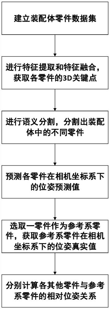
[0045] see figure 1 , a method for monitoring relative pose estimation of assembly parts based on deep learning, including the following steps:

[0046] Establish the assembly part data set, use the camera to move the surrounding ball along the target assembly, shoot the target assembly at a certain angle at intervals, obtain images of the target assembly at different angles, and generate different parts in the assembly through the collected images Corresponding point cloud data set, establish a sample data set;

[0047]Select 3D key points, load the sample data set into the deep learning network (in this example, a special extraction network is used) for feature extraction, obtain the surface information and geometric information of each part in the target assembly, and analyze the surface information of each part Perform feature fusion with geometric information to obtain the point-by-point features of each part; perform 3D key point detection on the point-by-point features...

Embodiment 2

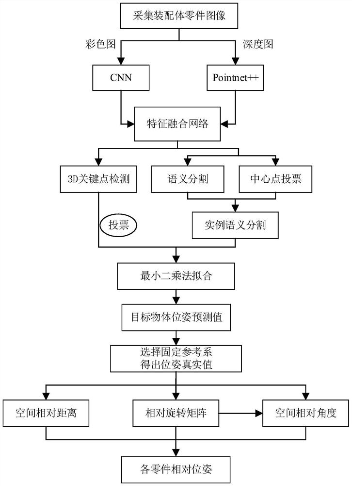
[0054] Further, see figure 2 , in this embodiment, the image includes a depth map and a color map, and the scene registration is performed through the depth map and the color map, and the gray value of each pixel in the depth map indicates the distance from a certain point in the scene to the camera, reflecting the scene According to the geometry of the surface of the visible object in the scene, according to a group of depth images obtained by shooting, the scene is reconstructed through the coordinate conversion of the pcl function library, and the point cloud data of the scene object is obtained; the scene includes multiple target objects, and the point cloud is repeatedly cropped using meshlab software , remove the background information and messy information in the scene, and then generate the 3D model of the assembly in the initial frame coordinate system. The 3D model of the assembly includes the 3D model of each part; the 3D model of the part includes each The coordin...


PUM


Abstract

The invention relates to an assembly part relative pose estimation monitoring method based on deep learning, and the method comprises the following steps: shooting images of a target assembly at different angles through a camera, and building a sample data set through the collected images; performing feature extraction and 3D key point detection on the sample data set through a deep learning network to obtain a 3D key point set of each part in the assembly; carrying out semantic segmentation according to the collected image, and distinguishing different parts in the image; according to the 3D key point set and the point cloud data set of each part, using a least square fitting algorithm to obtain a pose prediction value of each part under a camera coordinate system; selecting a part as a reference system part, establishing a world coordinate system by taking the geometric center of the reference system part as an original point, and calculating a pose true value of the reference system part under a camera coordinate system; and respectively calculating a relative pose relationship between each other part and the reference system part, wherein the relative pose relationship comprises a spatial geometric distance, a relative rotation matrix and a relative angle.

Description

technical field [0001] The invention relates to a method for estimating and monitoring relative poses of assembly parts based on deep learning, which belongs to the technical fields of computer vision and intelligent manufacturing. Background technique [0002] Computer vision is of great significance to the reform and upgrading of intelligent manufacturing, especially the emergence of deep learning networks has promoted the development of modern industry. In traditional manual assembly operations, workers need to compare the assembly process drawings. The assembly information is cumbersome and the degree of visualization is low, resulting in difficulties for workers to understand and low assembly efficiency. At the same time, it is necessary to check the assembly quality of the assembly. The inspection process is complicated and there are many review information records. It is time-consuming and labor-intensive to record mainly in paper documents, and it is easy to cause er...

Claims


Application Information

Patent Timeline
Patent Type & Authority Applications(China)
IPC IPC(8): G06T7/00G06T7/73G06T7/66
CPCG06T7/0004G06T7/75G06T7/66G06T2207/10024G06T2207/10028G06T2207/20084G06T2207/20081G06T2207/30164Y02P90/30
Inventor 陈成军李长治潘勇李东年洪军
Owner QINGDAO TECHNOLOGICAL UNIVERSITY
Why Eureka
Try Eureka