Signal transmission effect testing device for computer communication and use method

A technology for signal transmission and effect testing, applied in transmission systems, coupling devices, digital transmission systems, etc., can solve the problems of lack of straightening of the line, affecting the signal transmission effect, loosening of the crystal head and the plug interface, etc., to prevent the connection The effect of loosening and preventing the twists and turns of the network cable

Inactive Publication Date: 2021-05-14
INFORMATION CENT OF CHINA NORTH IND GRP
View PDF5 Cites 0 Cited by
  • Summary
  • Abstract
  • Description
  • Claims
  • Application Information

AI Technical Summary

Problems solved by technology

[0004] The present invention aims to solve the problem of the existing computer communication signal transmission effect testing device. The crystal head and the socket outlet are prone to looseness, resulting in inaccurate signal transmission effect detection, and the appearance of network cables after wrinkles will also affect signal transmission. Effect, the problem that it does not have the function of straightening along the line

Method used


Image

  • Signal transmission effect testing device for computer communication and use method
  • Signal transmission effect testing device for computer communication and use method
  • Signal transmission effect testing device for computer communication and use method

Examples


Embodiment Construction

[0034] The preferred embodiments of the present invention will be described below in conjunction with the accompanying drawings. It should be understood that the preferred embodiments described here are only used to illustrate and explain the present invention, and are not intended to limit the present invention.

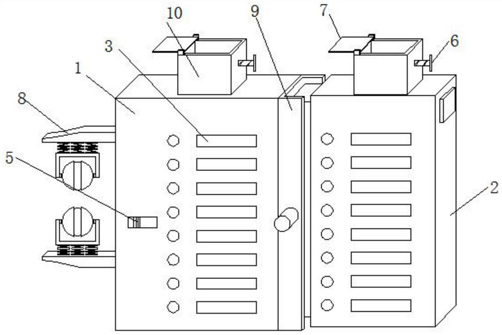
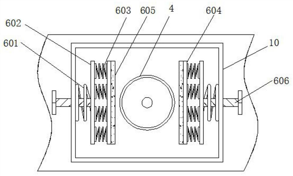
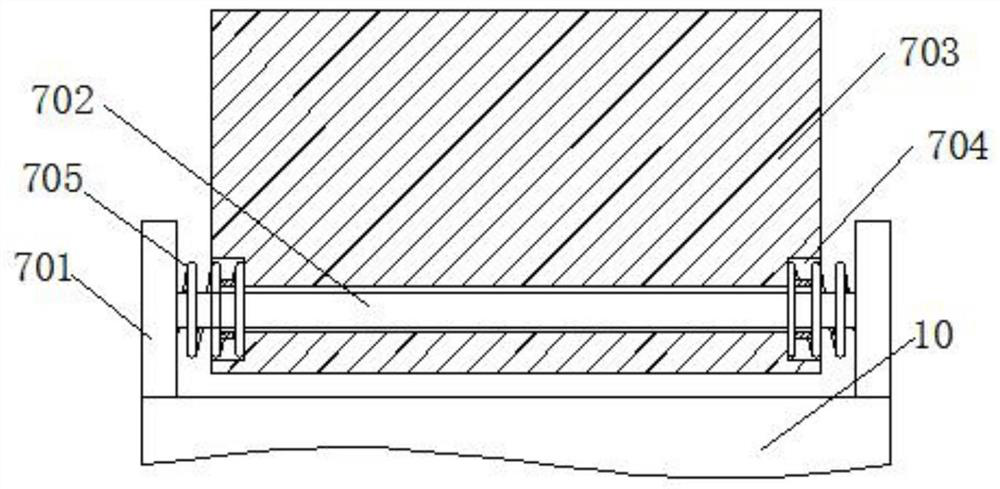
[0035] like Figure 1-Figure 5 As shown, a computer communication signal transmission effect test device includes a detector main unit 1 and a detector auxiliary unit 2, and is characterized in that: the front faces of the detector main unit 1 and the detector auxiliary unit 2 are fitted with display lights 3, and the top of the detector main unit 1 and the detector auxiliary unit 2 are fixedly connected with the plug interface 4, the front end of the detector main unit 1 is fitted with a control switch 5, and the top of the detector main unit 1 and the detector auxiliary unit 2 are fixed A sleeve 10 is connected, and a connection stabilization mechanism 6 is instal...


PUM


Abstract

The invention relates to a signal transmission effect testing device for computer communication, which comprises a detector main machine and a detector auxiliary machine, and is characterized in that the front end surfaces of the detector main machine and the detector auxiliary machine are connected with display lamps in an embedded manner, and the top ends of the detector main machine and the detector auxiliary machine are fixedly connected with plugging ports; the front end face of the detector main machine is connected with a control switch in an embedded mode. According to the invention, under the action of the connection stabilizing mechanism, the distance between two supporting plates can be adjusted by rotating the first hand-screwing bolt, and the clamping plates mounted on the surfaces of the two supporting plates can clamp and fix a rigistered jack plugged with the plugging port, so that the rigistered jack and the plugging port can be connected more stably, detection value deviation caused by connection looseness is prevented. Through a preset second compression spring, the tightness of the clamping plate for extruding the rigistered jack can be adjusted, and through cooperation with a latex plate on the surface of the clamping plate, the phenomenon that the rigistered jack is damaged due to excessive extrusion force of the clamping plate can be prevented.

Description

technical field [0001] The invention relates to a signal transmission effect testing device for computer communication, which belongs to the technical field of signal transmission testing equipment. Background technique [0002] "Communication" means that information is transmitted from point A to point B. Communication technology can be simple or complex. The existing ones are wired transmission and wireless transmission. Usually wired transmission refers to the transmission medium used to transmit data. Common network lines include optical fiber and network cable. The network cable is plugged between the crystal head and the device. There are two connection methods, one is the direct connection method, and the other is the cross connection method. The network detector connects the two ends of the transmission line to test the signal transmission effect. [0003] The existing computer communication signal transmission effect testing device, in the process of its use, the c...

Claims


Application Information

Patent Timeline
Patent Type & Authority Applications(China)
IPC IPC(8): H01R13/639H01R13/52H04L12/26
CPCH01R13/5213H01R13/639H01R2201/20H04L43/50
Inventor 王宇龙杨荫钊孙亚东武伟肖正秀谢武德何新刘宇坤王宇雷
Owner INFORMATION CENT OF CHINA NORTH IND GRP
Why Eureka
Try Eureka