High-precision synchronous motor

A high-precision synchronous and casing technology, which is applied in the manufacture of motor generators, electrical components, electromechanical devices, etc., can solve the problems of high-precision synchronous motors that cannot meet the assembly accuracy requirements of the casing, and the high defective rate of casings and end covers , Low coordination between the motor cover plate and the casing, to achieve the effects of improving stability and reliability, easy promotion, and guaranteed concentricity

Pending Publication Date: 2021-05-14
东莞市立意科技有限公司
View PDF0 Cites 0 Cited by
  • Summary
  • Abstract
  • Description
  • Claims
  • Application Information

AI Technical Summary

Problems solved by technology

[0003] However, in the small claw-pole synchronous motor structure, limited by the manufacturing process level of the casing and end cover, it is difficult for the casing and end cover of the synchronous motor to meet its high-precision requirements, especially in large-scale high-precision synchronous motors. During the production process, the defect rate of the casing and the end cover is very high, which cannot meet the assembly accuracy requirements of the high-precision synchronous motor for the casing (to meet the assembly accuracy of the casing, the size error of the casing and the end cover needs to reach ±0.01mm) , it is easy to cause the fit between the motor cover plate and the casing to be too low due to insufficient dimensional accuracy of the casing and the end cover, which makes the assembled bearing eccentric, the motor shaft jumps greatly, and even locks the motor shaft and crashes

Method used


Image

  • High-precision synchronous motor
  • High-precision synchronous motor
  • High-precision synchronous motor

Examples


Embodiment Construction

[0020] The following are only preferred embodiments of the present invention, and therefore do not limit the protection scope of the present invention.

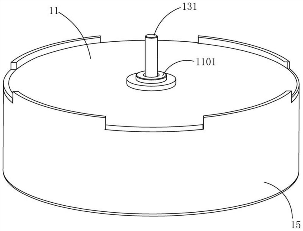
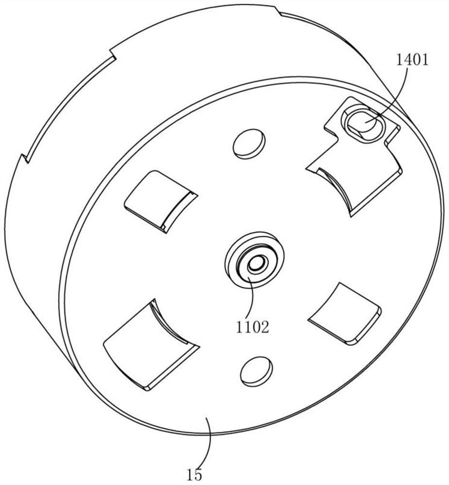
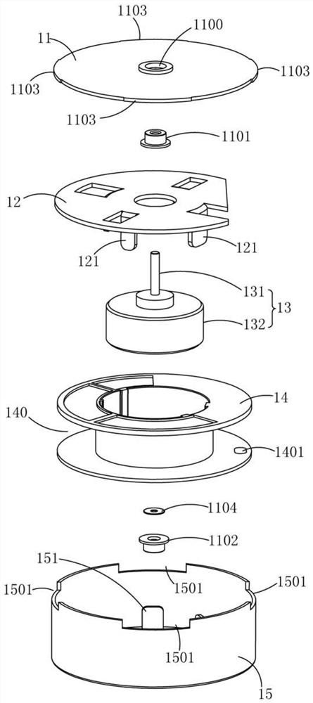
[0021] A high-precision synchronous motor, such as Figure 1 to Figure 6 As shown, it includes a casing 15, a rotor 13 disposed in the inner cavity of the casing 15, and a top cover 11 assembled on the casing 15. The rotor 13 includes an output shaft 131 having an output shaft 131 diameter d3, and the center position of the top cover 11 is set There is an upper bearing 1101 with a first inner diameter d1, the upper part of the output shaft 131 is movably inserted in the upper bearing 1101, the circumferential wall of the output shaft 131 and the inner ring wall of the upper bearing 1101 are clearance fit to form a matching width d11, satisfying the relationship 0.7≤ d11 / d1<1.15; a lower bearing 1102 with a second inner diameter d2 is provided at the center of the bottom of the casing 15, and the lower part of the output shaft...


PUM


Abstract

A high-precision synchronous motor is disclosed in the invention, and comprises a machine shell, a rotor arranged in the inner cavity of the machine shell and a top cover assembled on the machine shell, the rotor comprises an output shaft with the output shaft diameter d3, an upper bearing with the first inner diameter d1 is arranged at the center position of the top cover, and the upper portion of the output shaft is movably inserted into the upper bearing; the circumferential wall of the output shaft is in clearance fit with the inner ring wall of the upper bearing to form a fit width d11, and the relation that d11 / d1 is larger than or equal to 0.7 and smaller than 1.15 is met; a lower bearing with a second inner diameter d2 is arranged in the center of the bottom of the shell, and the lower part of the output shaft is movably inserted into the lower bearing; and the first inner diameter d1 is smaller than the second inner diameter d2, and the relation that d1 / d2 is larger than or equal to 0.97 and smaller than 0.99 is met. Compared with like motors in the prior art, the synchronous motor has the advantages that the bearing in the end cover can be used as a rotary support, the processing precision requirements of the casing and the cover plate are reduced, the yield of products is improved, and the fault probability of the motor is also reduced.

Description

technical field [0001] The invention relates to the technical field of synchronous motors, in particular to a high-precision synchronous motor. Background technique [0002] The claw-pole synchronous motor consists of two main components, the rotor and the stator. The stator includes a skeleton winding and a casing with claw poles on the periphery of the skeleton winding; an end cover is arranged at one end of the casing. The rotor assembly includes a magnetic steel made of permanent magnet material and a rotating shaft connected to it. A shaft sleeve is arranged on the outer periphery of the rotating shaft, and the shaft sleeve is fixedly connected to the end cover. After the skeleton winding is energized, The armature rotating magnetic field is generated in the air gap, and its rotation speed is synchronous speed. The interaction between the rotor magnetic field and the stator magnetic field, the rotor is dragged by the rotating magnetic field of the skeleton winding to ...

Claims


Application Information

Patent Timeline
Patent Type & Authority Applications(China)
IPC IPC(8): H02K5/16H02K15/16H02K5/04
CPCH02K5/04H02K5/165H02K15/165
Inventor 郭振华郭振宇
Owner 东莞市立意科技有限公司
Why Eureka
Try Eureka