Sludge mixing device for manufacturing ceramsite

A technology of mixing device and sludge, which is applied in mixers, mixers with rotary mixing devices, sludge treatment and other directions, can solve the problems of inability to realize continuous mixing of sludge and so on.

Pending Publication Date: 2021-05-18
新沂市新南环保产业技术研究院有限公司
View PDF0 Cites 0 Cited by
  • Summary
  • Abstract
  • Description
  • Claims
  • Application Information

AI Technical Summary

Problems solved by technology

[0003] The purpose of the present invention is to provide a sludge mixing device for producing ceramsite, to solve the problem that the existing sludge mixing device proposed in the above background technology cannot fully mix the dry sludge and the wet sludge, and the Dry sludge and wet s

Method used


Image

  • Sludge mixing device for manufacturing ceramsite
  • Sludge mixing device for manufacturing ceramsite
  • Sludge mixing device for manufacturing ceramsite

Examples


Example Embodiment

[0019] Example 1

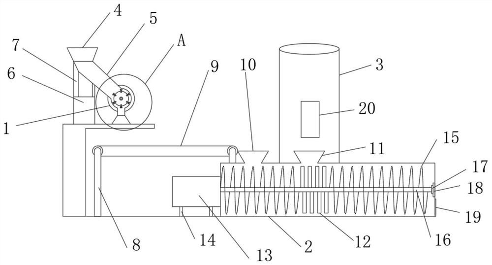
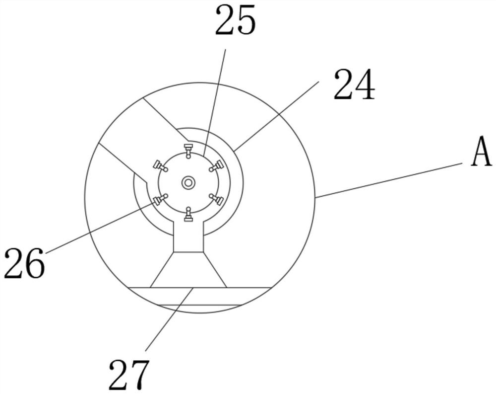
[0020] A sludge mixing device for producing ceramsite. In order to solve the problem that the existing sludge mixing device cannot fully mix dry sludge and wet sludge, dry sludge and wet sludge will appear at the discharge port. The problem of the situation where the sludge appears one after another, as a preferred embodiment, such as figure 1 , figure 2 As shown in Figure 3, it includes a pulverizer 1 and a mixing chamber 2. A dried sludge delivery pipe 5 is arranged on one side of the pulverizer 1, and a pulverizer feed port 4 is installed on the top of the dried sludge delivery pipe 5. The pulverizer 1 is provided with a dried sludge discharge port 23, the bottom of the dried sludge discharge port 23 is provided with a dried sludge conveyor belt 9, and the dried sludge conveyor belt 9 is fixed by a fixed rod 8, and the dried sludge A mixing chamber 2 is installed on the right side of the sludge conveyor belt 9, a dry sludge feed port 10 is provided on ...


PUM


Abstract

The invention belongs to the technical field of sludge treatment and relates to a sludge mixing device for manufacturing ceramsite. The device comprises a pulverizer and a mixing chamber; one side of the pulverizer is provided with a dried sludge conveying pipe; the top end of the dried sludge conveying pipe is provided with a pulverizer feed port; the bottom end of the pulverizer is provided with a dried sludge discharge port; a dried sludge conveying belt is arranged at the bottom of the dried sludge discharging port and fixed through a fixing rod; a mixing chamber is installed on the right side of the dried sludge conveying belt; a dried sludge feeding port is formed in one side of the top of the mixing chamber; a humidified sludge feeding port is formed in the middle of the top of the mixing chamber; a motor is arranged on the left side of the mixing chamber; the motor is fixed by a bearing base; a rotating shaft is horizontally arranged in the mixing chamber; one end of the rotating shaft is connected with the motor; the surface of the rotating shaft is sleeved with a propelling paddle and a stirring rod; the other end of the rotating shaft is fixed to an inner ring of a bearing. With the sludge mixing device adopted, the mixed stirring of dried sludge and wet sludge can be realized, and automatic degree of the devise is high.

Description

technical field [0001] The invention relates to the technical field of sludge treatment, in particular to a sludge mixing device for producing ceramsite. Background technique [0002] Sludge mixing technology is currently widely used in the field of sludge treatment. At present, the commonly used sludge mixing equipment includes drum type, screw type, centrifugal type, membrane type, paddle type, etc., for wet sludge with a moisture content of more than 90%. When it is carried out directly, there will be a viscous zone in the sludge, and the cohesive force and adhesion of the sludge are relatively large, resulting in a decrease in the drying rate of the sludge and an increase in the stirring power, which greatly increases the workload of the dryer and also causes transmission. The heat will deteriorate and pose a safety hazard. Mixing the dried sludge with the wet sludge with high moisture content reduces the moisture content of the sludge, improves the viscosity characte...

Claims


Application Information

Patent Timeline
IPC IPC(8): B01F7/04B01F7/08B01F13/10B02C17/16C02F11/00
CPCB02C17/163C02F11/00B01F27/72B01F27/70B01F33/831B01F33/83612
Inventor 张寅清李尧唐景春
Owner 新沂市新南环保产业技术研究院有限公司
Why Eureka
Try Eureka