
Flocculant mixing pipe for sludge treatment equipment
A sludge treatment and flocculant technology, which is applied in the direction of dehydration/drying/thickened sludge treatment, mixers, mixers with rotating stirring devices, etc., can solve the problem of sludge preparation tanks occupying a large area and investment, and the mixing effect Unsatisfactory problems, to achieve fast speed, good mixing effect, continuous mixing effect
- Summary
- Abstract
- Description
- Claims
- Application Information
AI Technical Summary
Problems solved by technology
Method used
Image

Examples
Embodiment Construction
[0010] The specific embodiments of the present invention will be further described below in conjunction with the accompanying drawings.
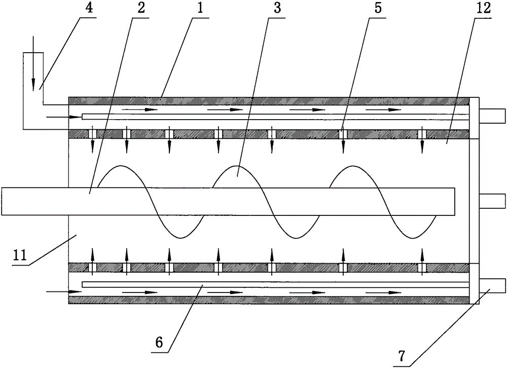
[0011] like figure 1 As shown, the flocculant mixing tube of the sludge treatment equipment of this embodiment includes a fixedly installed pipe sleeve 1 and a stirring shaft 2 movably installed in the pipe sleeve 1. The stirring shaft 2 has a spiral blade 3; the pipe sleeve 1 The pipe wall has a hollow structure, and one end of the pipe wall is installed with a flocculant introduction pipe 4, and the inner wall of the pipe sleeve 1 is provided with through holes 5 communicating with the inner cavity of the pipe wall at intervals, and the distance between adjacent through holes 5 is from the pipe wall. The feed end 11 of the sleeve 1 gradually increases toward the discharge end 12; a plurality of guide rods 6 are arranged in the pipe wall of the sleeve 1, and a guide motor 7 is installed at the end of the guide rod 6, and a plurality of guid...
PUM
 Abstract
Description
Claims
Application Information