Novel mixing pipe for sludge purifying equipment

A technology of purification equipment and mixing pipe, applied in the direction of dewatering/drying/concentrating sludge treatment, etc., can solve the problems of unsatisfactory mixing effect, large area of ​​sludge conditioning tank and large investment, and achieve better mixing effect and speed. Fast, good mixing results

Inactive Publication Date: 2017-01-11
无锡威胜环保设备制造有限公司
View PDF2 Cites 0 Cited by
  • Summary
  • Abstract
  • Description
  • Claims
  • Application Information

AI Technical Summary

Problems solved by technology

However, the sludge preparation tank occupies a relatively large area and investment, and the mixing of flocculant and sludge generally uses a low-speed paddle agitator or a hyperboloid agitator, and the mixing effect is not ideal.

Method used


Image

  • Novel mixing pipe for sludge purifying equipment

Examples


Embodiment Construction

[0010] The specific embodiments of the present invention will be further described below in conjunction with the accompanying drawings.

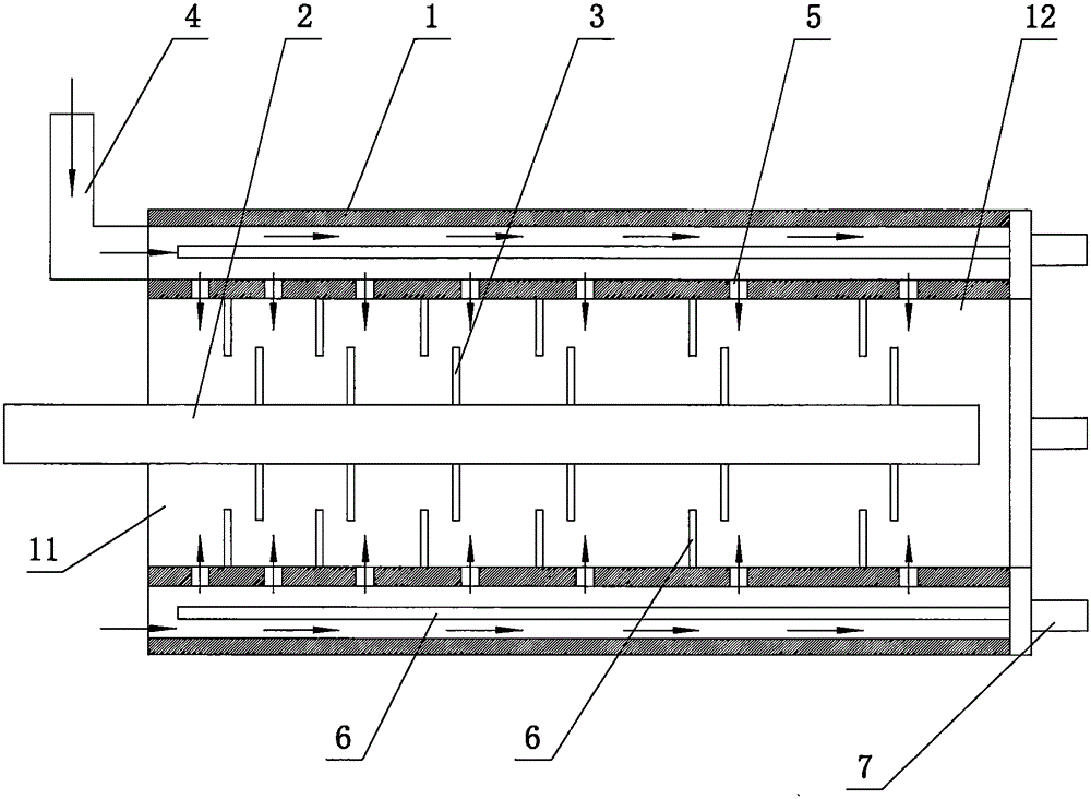
[0011] Such as figure 1 As shown, the new mixing tube of the sludge purification equipment of this embodiment includes a fixedly installed pipe sleeve 1 and a stirring shaft 2 movably installed in the pipe sleeve 1. The stirring shaft 2 has inner blades 3, and the pipe sleeve 1 The outer blade 8 is installed on the inner wall, and the inner blade 3 and the outer blade 8 are arranged at a staggered interval; the pipe wall of the pipe sleeve 1 has a hollow structure, and a flocculant introduction pipe 4 is installed on one end of the pipe wall, and the inner wall of the pipe sleeve 1 There are through holes 5 communicating with the inner cavity of the pipe wall at intervals, and the distance between adjacent through holes 5 gradually increases from the feed end 11 of the pipe sleeve 1 to the discharge end 12; the pipe wall of the pipe sleeve 1...


PUM


Abstract

The invention relates to a novel mixing pipe for sludge purifying equipment. The novel mixing pipe comprises a fixedly installed pipe sleeve and a stirring shaft movably installed in the pipe sleeve, wherein the stirring shaft is provided with inner blades, the inner wall of the pipe sleeve is provided with outer blades, and the inner blades and outer blades are arranged alternately in a staggered mode; the pipe wall of the pipe sleeve is provided with a hollow structure, one end of the pipe wall is provided with a flocculant introduction pipe, the inner wall of the pipe sleeve is provided with through holes at intervals which communicate with the inner cavity of the pipe wall, and the intervals between every two adjacent through holes gradually increase from the feed end to the discharge end of the pipe sleeve; and a plurality of guide rods are arranged in the pipe wall of the pipe sleeve, the end of each guide rod is provided with a guide motor, and the guide rods are symmetrically arranged around the central axis of the pipe sleeve. The pipeline gradual-change introduced flocculant is mixed with the sludge, so the novel mixing pipe has the advantages of favorable mixing effect, high speed and high efficiency, and implements continuous mixing. The inner and outer blades are used for stirring in a staggered mode, so the mixing effect is better.

Description

technical field [0001] The invention relates to the technical field of environmental protection equipment, in particular to a sludge treatment device. Background technique [0002] Before sludge dehydration, sludge conditioning should be carried out. The so-called sludge conditioning is also called chemical conditioning of sludge. Sludge concentration generally can only reduce the water content to about 85%. To further reduce the water content and volume, it is necessary to separate the bound water in the sludge, that is, to weaken the adhesion of this part of water to solid particles. Make the particles unstable and grow up. The common practice now is to set up a sludge conditioning tank before the sludge filter press to chemically condition the sludge, adding ferric chloride, lime and other organic and inorganic flocculants. The sludge flocculation time of the flocculants is generally 5- 10min. However, the sludge preparation tank occupies a relatively large area and in...

Claims


Application Information

Patent Timeline
Patent Type & Authority Applications(China)
IPC IPC(8): C02F11/14
Inventor 姚其英
Owner 无锡威胜环保设备制造有限公司
Why Eureka
Try Eureka