High-end manufacturing automatic metal column tapping equipment

A metal column, high-end technology, applied in the field of high-end manufacturing automated metal column tapping equipment, can solve problems such as low efficiency, time-consuming and laborious

Inactive Publication Date: 2021-05-18
盐城市千钧贸易有限公司
View PDF0 Cites 1 Cited by
  • Summary
  • Abstract
  • Description
  • Claims
  • Application Information

AI Technical Summary

Problems solved by technology

[0006] In order to overcome the time-consuming, labor-intensive, and low-efficiency shortcomings of manually pushing the fixture, the technical problem to be solve

Method used


Image

  • High-end manufacturing automatic metal column tapping equipment
  • High-end manufacturing automatic metal column tapping equipment
  • High-end manufacturing automatic metal column tapping equipment

Examples


Embodiment 1

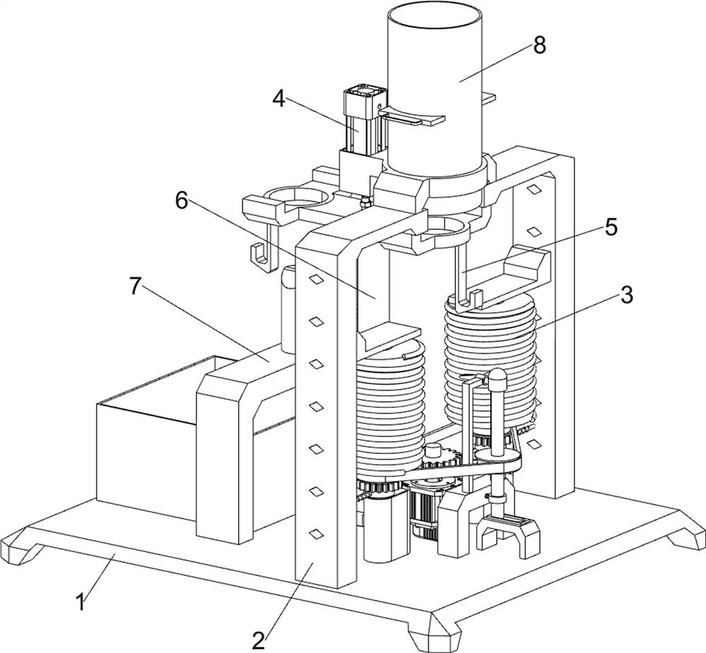
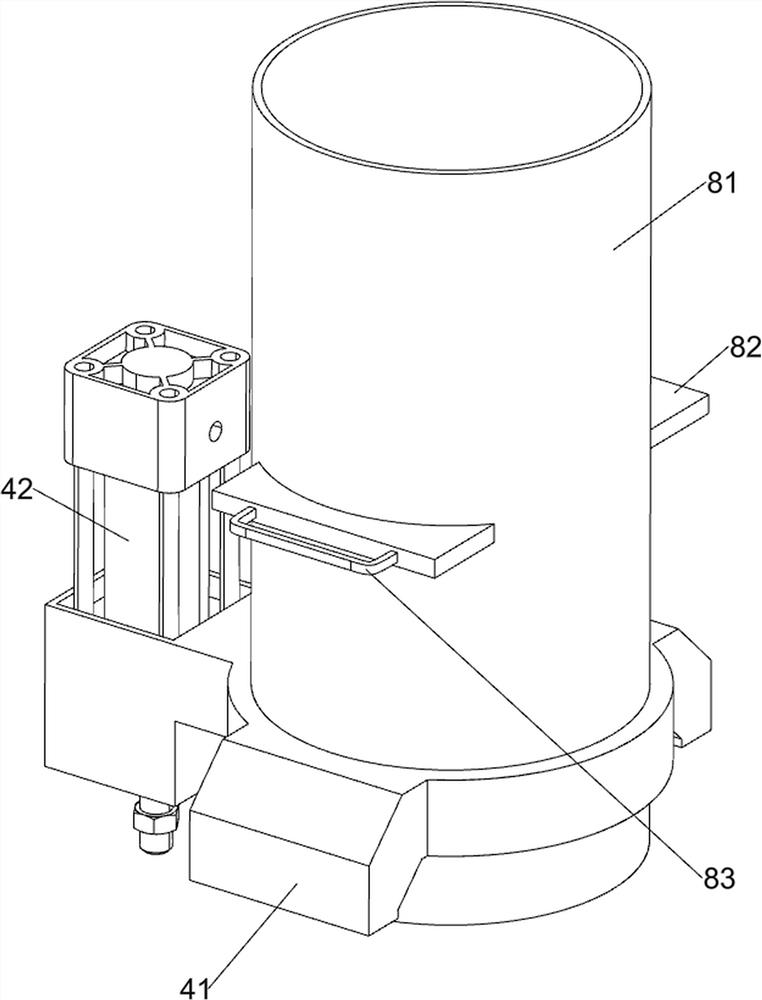
[0030] A high-end manufacturing automated metal column tapping equipment, such as figure 1 and figure 2 As shown, it includes a top plate 1, a support plate 2, a tapping assembly 3 and a pressing assembly 4. The support plate 2 is connected to the front and rear sides on the right side of the top plate 1, and the tapping assembly 3 is connected to the top right side of the top plate 1. Both sides The upper part of the support plate 2 is connected with a pressing assembly 4 .

[0031] The tapping assembly 3 includes a high-speed motor 31, a first gear 32, a fixed block 33, a roller 34, a slide bar 35, a transmission assembly 36 and a second gear 37, and a high-speed motor 31 is installed in the middle of the right side of the top plate 1, and the high-speed motor 31 outputs The shaft is connected with a first gear 32, the front and rear sides of the right part of the top plate 1 are connected with fixed blocks 33, the tops of the fixed blocks 33 on both sides are slidably con...

Embodiment 2

[0035] On the basis of Example 1, such as image 3 As shown, a clamping assembly 5 is also included, and the clamping assembly 5 includes a second bracket 51, a wedge-shaped rod 52, a first telescopic rod 53, a first spring 54, a second telescopic rod 55, a second spring 56 and a special-shaped rod 57, the middle of the right side of the top plate 1 is connected with a second support 51, the upper part of the second support 51 is slidably connected with a wedge bar 52, the right side of the wedge bar 52 is connected with the slide bar 35, and the right side of the second support 51 is slidably connected with a second A telescopic link 53, the first telescopic link 53 is connected with the first spring 54 between the second support 51, and the inner side of the bottom of the support plate 2 on both sides is slidably connected with the second telescopic link 55, the second telescopic link 55 is connected with the two A second spring 56 is connected between the support plates 2 o...

Embodiment 3

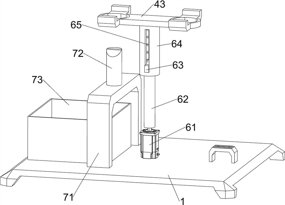
[0038] On the basis of Example 2, such as Figure 4 As shown, a rotating assembly 6 is also included. The rotating assembly 6 includes a servo motor 61, a rotating shaft 62, a spline 63, a bushing 64 and a third spring 65. A servo motor 61 is installed in the middle of the top plate 1, and the output shaft of the servo motor 61 is connected to There is a rotating shaft 62, the top of the rotating shaft 62 is connected with a spline 63, the bottom of the pressing plate 43 is connected with a shaft sleeve 64, the shaft sleeve 64 is slidably connected with the spline 63, and the third spring 65 is connected between the shaft sleeve 64 and the spline 63.

[0039] After the processing of the metal column is completed, the rotation of the servo motor 61 is manually activated to drive the rotation of the shaft 62, the rotation of the shaft 62 drives the rotation of the spline 63, the rotation of the spline 63 drives the rotation of the shaft sleeve 64, and the rotation of the shaft sl...


PUM


Abstract

The invention relates to tapping equipment, in particular to high-end manufacturing automatic metal column tapping equipment. The technical aim to be achieved by the invention is to provide the high-end manufacturing automatic metal column tapping equipment capable of automatically tapping and taking down a metal column. In order to achieve the technical aim, the high-end manufacturing automatic metal column tapping equipment provided by the invention comprises a top plate connected with a support plate, a tapping assembly connected to the top plate, and a downward pressing assembly connected to the support plate. Through cooperation of the tapping assembly and the downward pressing assembly, downward pressing and tapping are conducted on the metal column, and through a clamping assembly, it is not needed to manually pull a sliding rod to move rightwards to conduct tapping on the metal column.

Description

technical field [0001] The invention relates to a tapping device, in particular to a high-end manufacturing automation metal column tapping device. Background technique [0002] Tapping refers to screwing the tap into the bottom hole to be drilled with a certain torque to process the internal thread. "Rigid tapping" is also called "synchronous feed tapping". It is very important to choose a suitable lubricant in tapping. [0003] At present, people tap the metal column by manually installing the tapping roller on the electric drill, then installing the metal column on the clamp, and the spring manually pushes the clamp to make the metal column contact with the tapping roller to perform tapping. It is time-consuming, labor-intensive and inefficient to manually push the fixture all the time. [0004] Therefore urgently need to develop a kind of high-end manufacturing automation metal column tapping equipment that can automatically tap metal column and take off. Contents o...

Claims


Application Information

Patent Timeline
IPC IPC(8): B21H3/04
CPCB21H3/04
Inventor 任帅龙
Owner 盐城市千钧贸易有限公司
Why Eureka
Try Eureka