Elevator decoration part cutting device

A cutting device and decoration technology, which is applied in the direction of positioning device, feeding device, maintenance and safety accessories, etc., can solve the problems that the decoration board 14 cannot be cut flexibly, and the flexibility is not enough.

Inactive Publication Date: 2021-05-18
方冬荣
View PDF10 Cites 2 Cited by
  • Summary
  • Abstract
  • Description
  • Claims
  • Application Information

AI Technical Summary

Problems solved by technology

[0003] In the current cutting device for elevator decoration parts, a baffle plate is fixedly arranged on the upper side between the front and rear two support rods, and two No. The No. 1 slider is set, and the right side wall of the No. 1 slider is fixedly arranged on the No. 1 fixing plate, and the No. 2 fixing plate and the No. 3 fixing plate are fixedly arranged on the right side wall of the No. 1 fixing plate from top to bottom. A cylinder is fixedly arranged on the lower side wall of the No. 2 fixed plate. After the piston rod of the cylinder moves through the No. 3 fixed plate, it is fixedly connected with the No. 4 fixed plate. The lower side wall of the No. There is a No. 1 motor. The output shaft of the No. 1 motor is fixed with a coupling, and the coupling is equipped with a cutting piece. However, in the process of cutting the decorative parts, the adjustment flexibility of this device is not enough. According to the actual cutting needs, the decoration board 14 can be fully and flexibly cut. For this reason, a cutting device for elevator decoration parts is now provided to solve the above technical problems

Method used


Image

  • Elevator decoration part cutting device
  • Elevator decoration part cutting device
  • Elevator decoration part cutting device

Examples


Embodiment 1

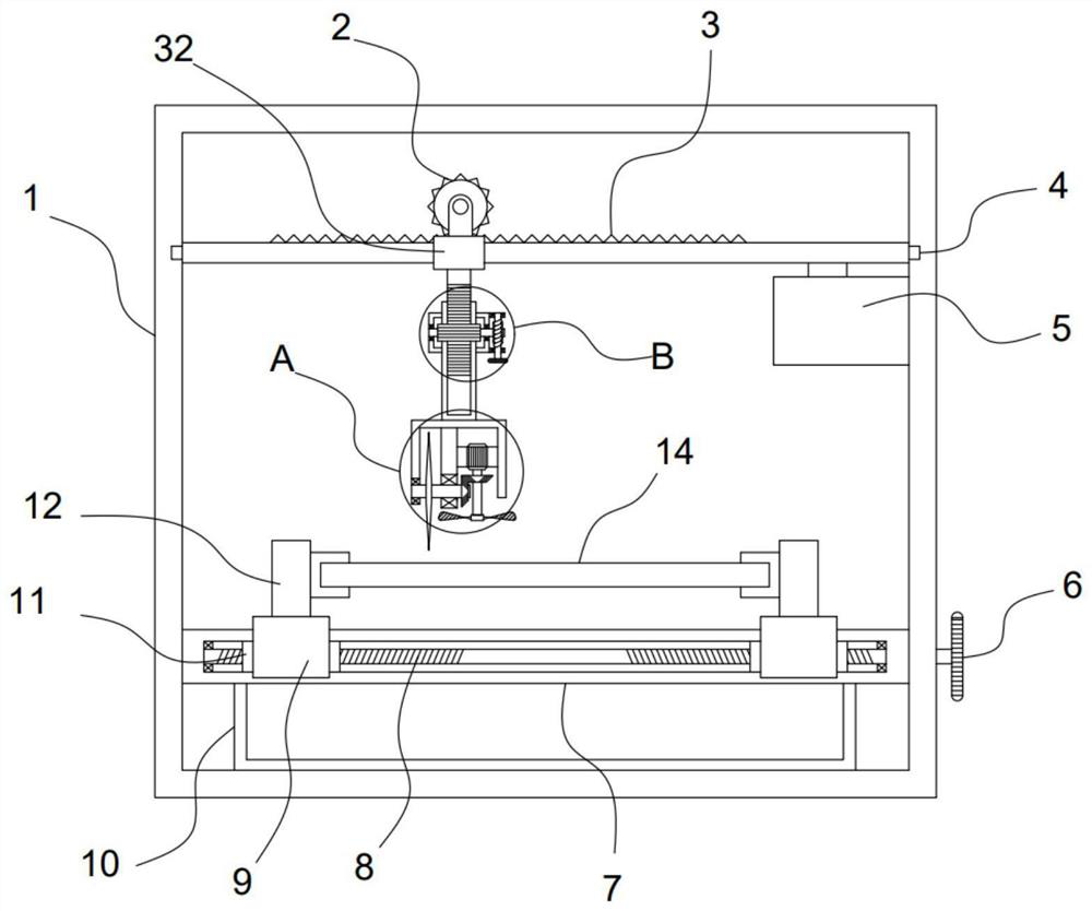
[0024] see Figure 1-5 , a cutting device for elevator decoration parts, comprising a fixed frame 1, a support frame 7 is fixed on the fixed frame 1, a collection tank 10 is fixed on the bottom of the support frame 7, a hand wheel 6 is installed on the fixed frame 1, and a hand wheel 6 The upper drive is connected with a clamping mechanism installed on the supporting frame 7, and a pair of clamping seats 12 are connected to the clamping mechanism to fit the decorative board 14. The transmission box 5 is fixed on the fixed frame 1, and the transmission box 5. The upper drive is connected with a translation mechanism, which is driven and connected with a horizontal rack 3. An adjustment mechanism is slidably installed on the horizontal rack 3. A vertical rack 23 is vertically fixed at the bottom of the adjustment mechanism. The sliding sleeve on the bar 23 is provided with a lifting mechanism, and a cutting mechanism for cutting the decorative board 14 is installed at the bottom...

Embodiment 2

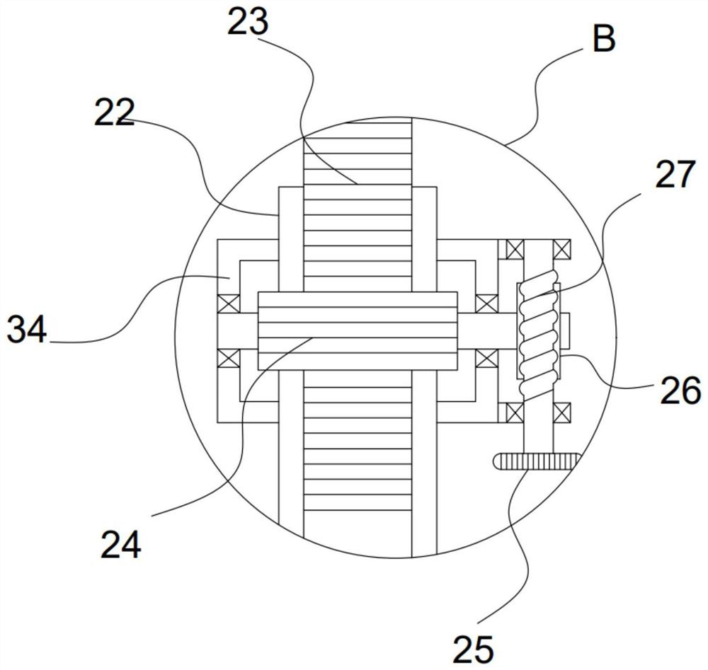
[0030] On the basis of Embodiment 1, in addition, this device is also provided with a translation mechanism, including a servo motor 31 fixed in the transmission box 5, and an incomplete bevel gear 30 is driven and connected to the servo motor 31, and the transverse rack 3. The bottom is fixed with a threaded cover block 29. The threaded cover block 29 is threaded with a reciprocating screw 28. The reciprocating screw 28 is sleeved with a bevel gear I13 and a bevel gear II15 that alternately mesh with the incomplete bevel gear 30.

[0031] The set servo motor 31 drives the incomplete bevel gear 30 to rotate, and the incomplete bevel gear 30 is meshed with the bevel gear I13 and the bevel gear II15 alternately. At this time, the reciprocating screw 28 rotates alternately clockwise and counterclockwise. At this time, the reciprocating screw 28 drives the threaded block 29 drives the transverse rack 3 to perform reciprocating motion, that is, the cutting mechanism realizes recipro...


PUM


Abstract

The invention discloses an elevator decoration part cutting device, and relates to the technical field of elevator part machining. A vertical rack is vertically fixed to the bottom of a fixing frame and the bottom of an adjusting mechanism, the vertical rack is slidably sleeved with a lifting mechanism, and a cutting mechanism used for cutting a decoration plate is installed at the bottom of the lifting mechanism. According to the cutting device, clamping seats are driven through an arranged clamping mechanism, the clamping and fixing effect of the two clamping seats on the decoration plate is achieved, the cutting process of the decoration plate is more stable, the height of a cutting blade can be adjusted according to the thickness of the decoration plate through the arranged vertical lifting mechanism, the complete cutting effect on the decoration plate is achieved, the arranged adjusting mechanism can drive an adjusting sliding sleeve to transversely move, so that the cutting blade flexibly adjusts the cutting portion of the decoration plate, an arranged translation mechanism can achieve reciprocating motion of the cutting blade in the cutting process, it is guaranteed that the decoration plate is completely cut, and the cutting quality and the cutting efficiency are greatly improved.

Description

technical field [0001] The invention relates to the technical field of elevator parts processing, in particular to a cutting device for elevator decoration parts. Background technique [0002] Elevator refers to the permanent transportation equipment that serves several specific floors in the building, and its car runs on at least two rigid rails that are perpendicular to the horizontal plane or at an inclination angle of less than 15° from the plumb line. There is also a step type, and the tread plate is installed on the crawler belt to run continuously, commonly known as an escalator or a moving walk. The fixed lifting equipment serving the specified floors, the size and structure of the car are convenient for passengers to enter and exit or to load and unload goods. [0003] In the current cutting device for elevator decoration parts, a baffle plate is fixedly arranged on the upper side between the front and rear two support rods, and two No. The No. 1 slider is set, an...

Claims


Application Information

Patent Timeline
IPC IPC(8): B23D79/00B23Q3/06B23Q5/28B23Q11/00
CPCB23D79/00B23Q3/06B23Q5/28B23Q11/005
Inventor 方冬荣
Owner 方冬荣
Why Eureka
Try Eureka