Energy conversion device and vehicle

A technology of energy conversion device and bridge arm, applied in the field of vehicles, can solve problems such as poor compatibility

Active Publication Date: 2021-05-18
BYD CO LTD
View PDF8 Cites 5 Cited by
  • Summary
  • Abstract
  • Description
  • Claims
  • Application Information

AI Technical Summary

Problems solved by technology

All in all, the compatibility of these DC charging methods is relatively poor

Method used


Image

  • Energy conversion device and vehicle
  • Energy conversion device and vehicle
  • Energy conversion device and vehicle

Examples


Embodiment Construction

[0028] Specific embodiments of the present disclosure will be described in detail below in conjunction with the accompanying drawings. It should be understood that the specific embodiments described here are only used to illustrate and explain the present disclosure, and are not intended to limit the present disclosure.

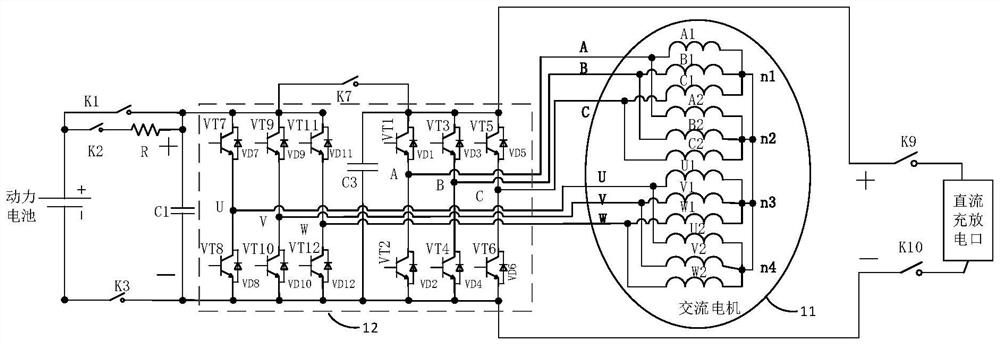
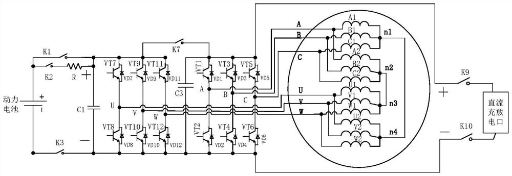
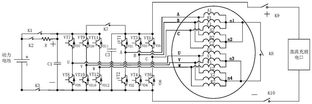
[0029] figure 1 A schematic structural diagram of an energy conversion device according to an embodiment of the present disclosure is shown. Such as figure 1As shown, the energy conversion device includes an AC motor 11, a bidirectional PWM inverter 12 and a switch module, wherein: the AC motor 11 includes x sets of windings, and all phase windings of each set of windings can be controlled by using the motor vector. In the operation of the AC motor described above, each set of windings is staggered by a certain electrical angle θ, where 2≤x, 0≤θ<360; the bidirectional PWM inverter 12 includes x sets of bridge arms, and each set of bridge arms is in phase wi...


PUM


Abstract

The invention relates to an energy conversion device and a vehicle, which can be compatible with various direct current charging and discharging modes and are low in cost. The energy conversion device comprises an alternating current motor, a bidirectional PWM inverter and a switch module, the alternating current motor comprises x sets of windings, all phases of windings of each set of windings are controlled through motor vectors to enable the alternating current motor to operate, and the windings are staggered by a certain electrical angle theta; the bidirectional PWM inverter comprises x groups of bridge arms, each group of bridge arms is connected with one set of windings, and the number of the bridge arms of each group of bridge arms is matched with the phase number of the windings connected with the bridge arms; the switch module comprises a first switch sub-module and a second switch sub-module, the first switch sub-module controls the electrical connection between the bus of one group of bridge arms and the direct current charging and discharging port, and the second switch sub-module controls the electrical connection between each group of bridge arms; and at least two sets of windings in the x sets of windings and the corresponding bridge arm groups jointly form a loop for charging and discharging the power battery.

Description

technical field [0001] The present disclosure relates to the field of vehicles, and in particular, relates to an energy conversion device and a vehicle. Background technique [0002] At present, DC charging of power batteries is generally divided into two types: direct charging and boost charging. Direct charging means that the positive and negative poles of the charging pile are directly connected to the positive and negative busbars of the power battery through a contactor or relay, and the battery is directly charged without a step-up or step-down circuit in the middle. Boost charging refers to adding a buck-boost DC / DC bridge circuit between the charging pile and the positive and negative bus bars of the power battery. [0003] For direct charging, when the maximum output voltage of the charging pile is lower than the voltage of the power battery, the charging pile cannot charge the power battery. For boost charging, since it is necessary to separately add a DC / DC brid...

Claims


Application Information

Patent Timeline
Patent Type & Authority Applications(China)
IPC IPC(8): B60L53/12B60L53/122H02P21/00H02P29/64H02M7/72
CPCB60L53/12B60L53/122H02P21/0003H02P29/64H02M7/72Y02T10/64
Inventor 潘华李吉成张宇昕雷野黄日
Owner BYD CO LTD
Why Eureka
Try Eureka