
Optical storage and charging multi-target power dynamic adjusting system and method

A dynamic adjustment, multi-objective technology, applied in information technology support systems, reducing/preventing power oscillations, power network operating system integration, etc. electricity and other issues

Active Publication Date: 2021-05-18
SHANGHAI ELECTRICGROUP CORP
View PDF6 Cites 2 Cited by
  • Summary
  • Abstract
  • Description
  • Claims
  • Application Information

AI Technical Summary

Problems solved by technology

[0002] With the increasing popularity of electric vehicles, more and more charging piles have been installed in public places such as residential quarters, parking lots, and power stations. However, too many charging piles connected to the grid may exceed the capacity limit of the grid transformer, which has a negative impact on the grid. cause harm, and the load of electric vehicles has a certain degree of randomness and dispersion. If a large number of electric vehicles use charging piles for charging, it will bring a huge power impact to the distribution network, and charging with a high penetration rate will affect the line. The node voltage, the normal operation of the equipment and the normal power consumption of the user

Method used


Image

  • Optical storage and charging multi-target power dynamic adjusting system and method
  • Optical storage and charging multi-target power dynamic adjusting system and method
  • Optical storage and charging multi-target power dynamic adjusting system and method

Examples


Embodiment Construction

[0044] In order to make the present invention more comprehensible, preferred embodiments are described in detail below with accompanying drawings.

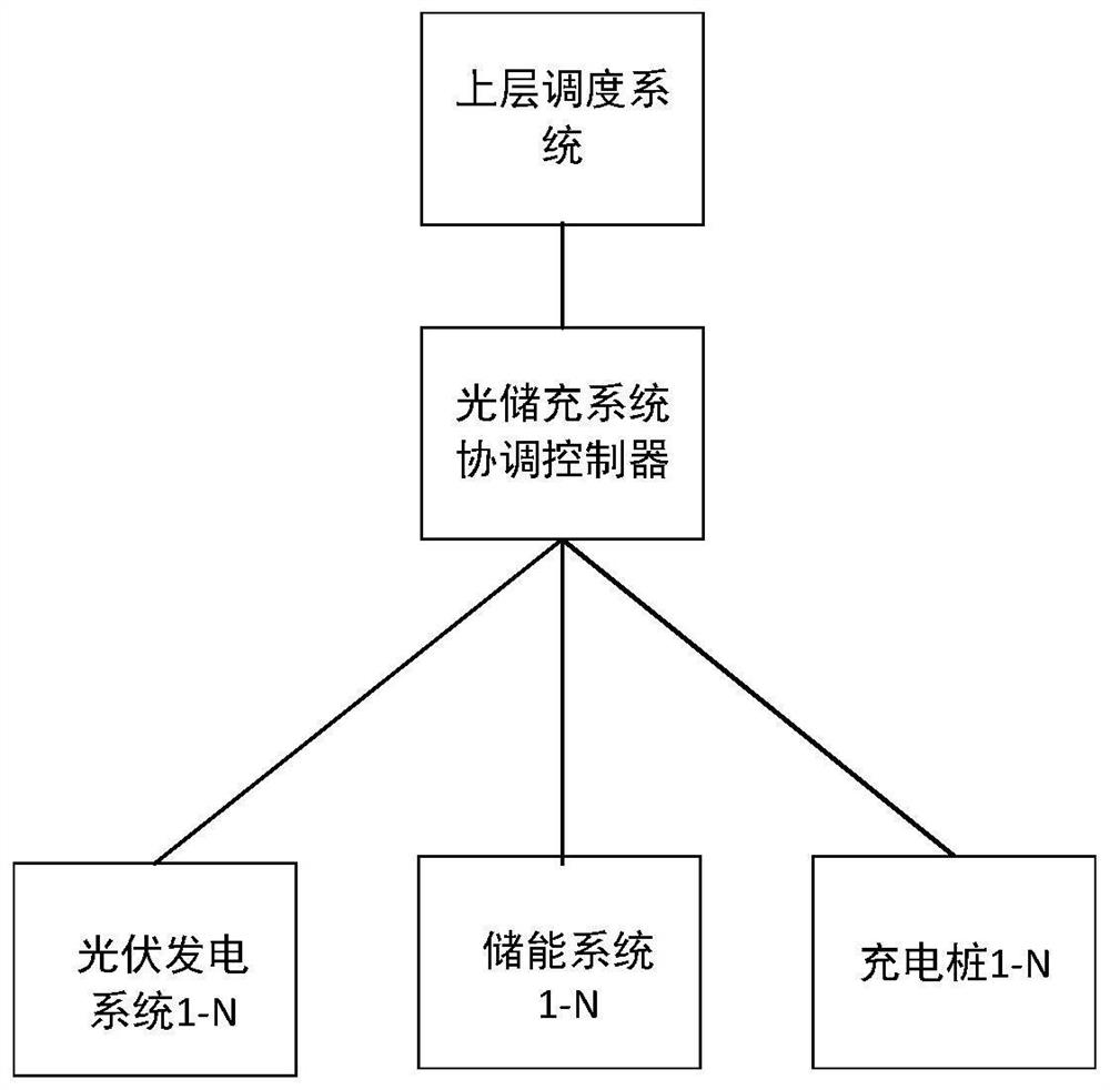
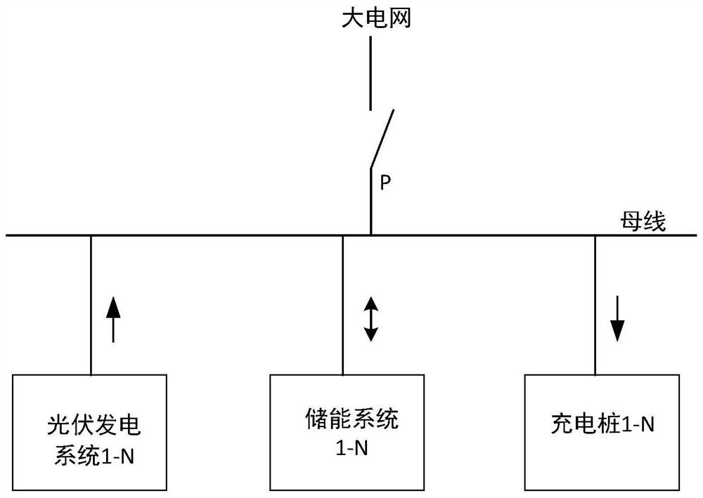
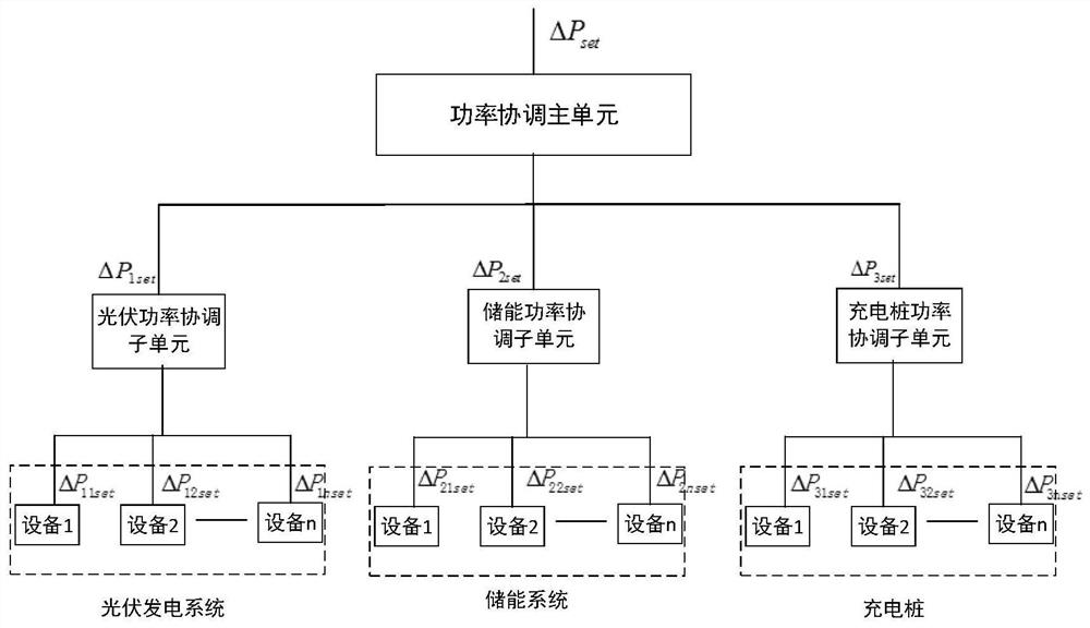
[0045] The structure diagram of a dynamic adjustment system for multi-target power of optical storage charging in the present invention is as follows figure 1, the system is divided into three layers, the equipment layer is composed of multiple photovoltaic power generation systems, multiple energy storage systems, and multiple charging piles, the solar storage and charge coordination controller is the control layer, and the upper dispatching system is the dispatching layer. The optical-storage-charge coordination controller collects information at the equipment layer, runs the power coordination algorithm according to the instructions of the scheduling layer, and controls the equipment in real time. In this three-layer structure, if the goal of the coordination controller of solar storage and charging is determined and unchanged,...


PUM


Abstract

The invention discloses an optical storage and charging multi-target power dynamic adjusting system and method, and the system is characterized in that the adjusting system comprises a control layer and an equipment layer, the equipment layer comprises a plurality of photovoltaic power generation systems, a plurality of energy storage systems and a plurality of charging piles, and the control layer comprises an optical storage and charging coordination controller. And the optical storage and charging coordination controller is used for collecting output power information of each piece of equipment of the equipment layer and performing real-time control on the power of each piece of equipment of the equipment layer, so that the power difference between the actual power value and the set power value of interaction between the optical storage and charging system and the power grid tends to zero. According to the invention, the energy flow value with the power grid can be self-defined, the method can be used for an off-grid system and a grid-connected system, the application scene is wide, and the target energy flow value of the optical storage and charging system at the grid-connected point can be flexibly set; the adjustment is fast and accurate, and the real-time performance is good. The optical storage and charging integrated system not only utilizes the generating capacity of renewable energy sources to the greatest extent, but also has good economic benefits.

Description

technical field [0001] The invention relates to a system and method for dynamically adjusting multi-objective power of optical storage charging, in particular to a system and method for dynamic coordination control of multi-objective optical storage charging power, belonging to the technical field of optical storage charging microgrid control systems. Background technique [0002] With the increasing popularity of electric vehicles, more and more charging piles have been installed in public places such as residential quarters, parking lots, and power stations. However, too many charging piles connected to the grid may exceed the capacity limit of the grid transformer, which has a negative impact on the grid. cause harm, and the load of electric vehicles has a certain degree of randomness and dispersion. If a large number of electric vehicles use charging piles for charging, it will bring a huge power impact to the distribution network, and charging with a high penetration rat...

Claims


Application Information

Patent Timeline
Patent Type & Authority Applications(China)
IPC IPC(8): H02J3/24H02J3/28H02J3/32H02J3/38B60L53/63B60L53/64B60L53/67B60L55/00
CPCH02J3/24H02J3/28H02J3/322H02J3/381H02J3/388B60L53/63B60L53/64B60L53/67B60L55/00H02J2300/24H02J2310/48H02J2310/64Y02T10/70Y02T10/7072Y02T90/12Y04S20/222Y02E70/30Y02E10/56Y02B70/3225
Inventor 吴洁奚玲玲崔寒冰缪勇陈国栋
Owner SHANGHAI ELECTRICGROUP CORP
Learn More