Driving control circuit structure for realizing dimming function

A technology for driving control circuits and functions, applied in the direction of energy-saving control technology, electrical components, etc., can solve problems affecting the accuracy of dimming

Active Publication Date: 2021-05-18
CRM ICBG (WUXI) CO LTD
View PDF7 Cites 1 Cited by
  • Summary
  • Abstract
  • Description
  • Claims
  • Application Information

AI Technical Summary

Problems solved by technology

Affect dimm

Method used


Image

  • Driving control circuit structure for realizing dimming function
  • Driving control circuit structure for realizing dimming function
  • Driving control circuit structure for realizing dimming function

Examples


Embodiment 1

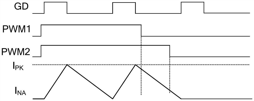
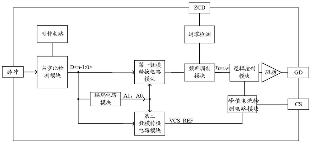
[0105] Embodiment 1 The output current is adjusted through the frequency modulation mode. The digital output signal and the two-bit control signal control the first digital-to-analog conversion circuit module circuit to generate a nonlinear changing current and a fixed current, and the current is output to the frequency modulation circuit to generate a delay signal. At this time, the system enters the intermittent working mode. By changing the working frequency of the power tube to change the duty cycle of the switch, and then change the average output current of the LED to realize the dimming effect of the LED.

[0106] Taking the two-bit control signal generated by the encoding circuit as an example, the duty cycle of the PWM signal is D, and the calculation formula of the duty cycle D is as follows:

[0107] D=D1×D2;

[0108] Among them, D1 is the output current ratio changed by switching delay, and D2 is the output current ratio adjusted by changing the reference voltage....

Embodiment 2

[0166] Embodiment 2 The output current is adjusted through the peak voltage. The digital signal output controls the second digital-to-analog conversion circuit module circuit to change the CS peak sampling voltage, and then changes the LED output current by changing the peak current of the inductor, so as to realize the dimming effect of the LED. Among them, D1, D2, I LED , f and the change relationship of PWM duty cycle as Figure 12 shown.

[0167] 2.1 Encoding circuit module:

[0168] The truth table of the encoding circuit module is as follows, taking n=12 as an example:

[0169] PWM duty cycle D (hexadecimal)

A1A0 100%~50% FFF~800 00 50%~12.5% 7FF~200 01 12.5%~6.25% 1FF~100 10 6.25%~0% 0FF~0 11

[0170] 2.2 The first digital-to-analog conversion circuit module:

[0171] Such as Figure 15 Shown is a schematic diagram of the voltage digital-to-analog conversion circuit DAC1_1 in the internal circuit of the first digital-t...


PUM


Abstract

The invention relates to a driving control circuit structure for realizing a dimming function. The driving control circuit structure comprises: a duty ratio detection module used for sampling and calculating an input pulse wave through a high-speed clock signal to obtain a group of digital output signals; a coding circuit module which is used for generating a two-bit control signal through the digital output signal; a first digital-to-analog conversion circuit module which is used for generating a non-linear change current and a fixed current, and further adjusting an output current through a frequency modulation mode; a frequency modulation circuit module; a second digital-to-analog conversion circuit module which is used for outputting voltage and further changing output current by changing peak voltage; a peak current detection circuit module; and a logic control circuit module. By adopting the driving control circuit structure for realizing the dimming function, the dimming precision and the dimming depth are effectively improved, and when the driving control circuit structure is applied to dimming and color modulation occasions, light felt by human eyes can achieve relatively soft changes in brightness and hue, and the brightness of a lamp can be adjusted to be darker at night.

Description

technical field [0001] The invention relates to the field of smart home, in particular to the field of LED dimming, and specifically refers to a driving control circuit structure for realizing the dimming function. Background technique [0002] The circuit structure of existing invention such as figure 1 As shown, the AC input power is rectified by the rectifier bridge and then filtered by capacitor C1 to generate DC power supply. Resistor R4 and capacitor C5 generate a low-voltage signal VCC to start the driver chip, and the internal circuit of the driver chip clamps VCC. After the circuit works normally, the power tube is turned on, and the primary side inductance N of the transformer T1 P The current rises gradually, the inductor stores energy, and the sampling resistor R CS To sample the inductor current, the sampling resistor R CS When the voltage on reaches VREF, the inductor current I L peak reaches I PK =VREF / R CS , the constant current logic control circuit co...

Claims


Application Information

Patent Timeline
IPC IPC(8): H05B45/325H05B45/14
CPCY02B20/40
Inventor 刘玉芳丁增伟曾洁琼张天舜罗先才
Owner CRM ICBG (WUXI) CO LTD
Why Eureka
Try Eureka