Axial displacement measuring equipment for knee joint cruciate ligament injury
A cruciate ligament, measuring equipment technology, applied in the directions of diagnostic recording/measurement, medical science, sensors, etc., can solve the problems of experience and force, lack of ligament stability, no unified standard, etc.
- Summary
- Abstract
- Description
- Claims
- Application Information
AI Technical Summary
Problems solved by technology
Method used
Image
Examples
Embodiment 1
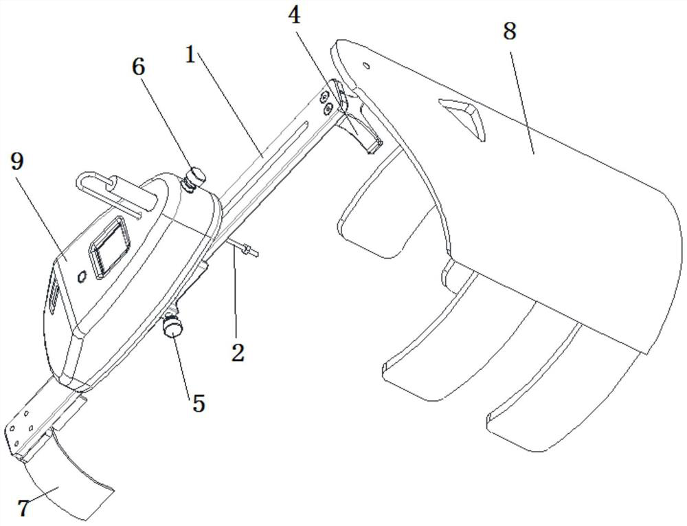
[0044] Such as figure 2 As shown, this embodiment provides a kind of axis displacement measurement device for knee cruciate ligament injury, including: guide plate 1, displacement sensor 2;
[0045] The lower end of the guide plate 1 is fixed on the calf and fits closely with the calf; the upper end of the guide plate 1 is fixed on the femoral condyle, and the support device arranged on the upper end of the guide plate 1 makes the The upper end of the guide plate 1 deviates from the patella and the tibia by a certain distance, so as to reserve a movable space for the tibia when measuring the axis displacement; the displacement sensor 2 is vertically arranged on the guide plate 1, and the The front end of the displacement sensor 2 abuts on the tibial tuberosity.
[0046] Specifically, in this embodiment, before measuring the cruciate ligament injury of the knee joint, it is first necessary to fix the axis displacement measurement device so that the axis displacement measureme...
Embodiment 2
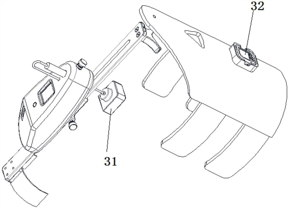
[0059] Such as image 3 As shown, the structure of this embodiment is basically the same as that of Embodiment 1, the difference is that, on the basis of Embodiment 1, this embodiment also adds a position tracker 3;
[0060] The position tracker 3 further includes: a first position tracker 31 and a second position tracker 32; the first position tracker 31 is fixed on the front end of the displacement sensor 2, and the second position tracker 32 It is fixed on the femur; the first position tracker 31 cooperates with the second position tracker 32 to obtain the bending angle of the tibia, and the acceleration of the tibial movement through the first position tracker 31 .
[0061] Specifically, in order to make the measurement of the degree of cruciate ligament injury more accurate, the present invention also adds a position tracker 3 on the basis of the displacement sensor 2 .
[0062] By cooperating with the two position trackers 3 respectively arranged at the front end of the...
Embodiment 3
[0068] The present embodiment provides 3 kinds of specific operation modes of the present invention, specifically as follows:
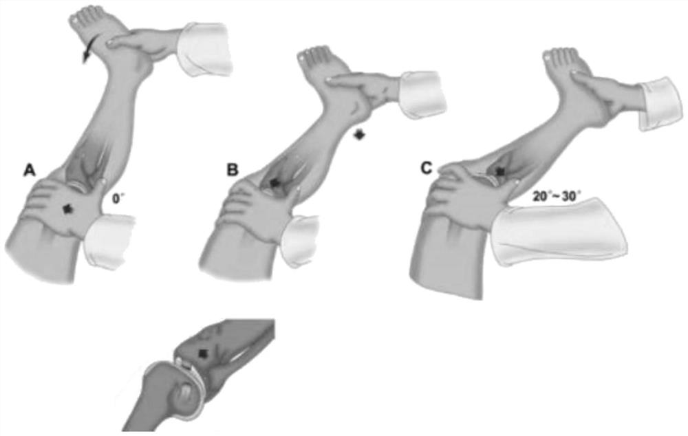
[0069] (1) Adjust the patient to the supine position, the examiner stands on the outside of the examined limb, passively straightens the knee joint, clicks the circular button on the instrument panel, and resets the display of the displacement sensor. Grip the heel with one hand to internally rotate the calf, and apply valgus stress to the proximal tibia with the other hand. The knee begins to bend gradually from 0 degrees of extension, and when the affected knee is out of the locked position, the lateral tibial condyle begins to gradually subluxate forward. When the knee is slowly bent for 30°-40° (the angle calculated by the position tracker), the tibia suddenly resets backward, check the displayed value and record the sudden change value (displacement and acceleration) to measure the degree of ligament damage.
[0070] (2) The patient lies on his ...
PUM
 Abstract
Description
Claims
Application Information
 - R&D
- Intellectual Property
- Life Sciences
- Materials
- Tech Scout
- Unparalleled Data Quality
- Higher Quality Content
- 60% Fewer Hallucinations
Browse by: Latest US Patents, China's latest patents, Technical Efficacy Thesaurus, Application Domain, Technology Topic, Popular Technical Reports.
© 2025 PatSnap. All rights reserved.Legal|Privacy policy|Modern Slavery Act Transparency Statement|Sitemap|About US| Contact US: help@patsnap.com


