
Selective laser melting equipment with reciprocating type conveying rail

A technology of selective laser melting and conveying track, which is applied to the separation of dispersed particles, chemical instruments and methods, combined devices, etc., which can solve the problems of inconvenient collection of metal powder, impact on the environment, and diffusion of metal powder

Inactive Publication Date: 2021-05-25
ANHUI TUO BAO ADDITIVE MFG TECH CO LTD
View PDF0 Cites 3 Cited by
  • Summary
  • Abstract
  • Description
  • Claims
  • Application Information

AI Technical Summary

Problems solved by technology

[0004] During the selective laser melting operation, metal powder will remain on the surface of the accumulated three-dimensional solid, and these metal powders can be used as raw materials for the next selective laser melting operation. Therefore, when cleaning, these metal powders need to be removed Collecting it can not only maintain the beauty of the three-dimensional entity, but also improve the utilization rate of resources. In the prior art, when such metal powder is collected, the metal powder will be diffused, affecting the surrounding environment, and it is not convenient collection of metal powder

Method used


Image

  • Selective laser melting equipment with reciprocating type conveying rail
  • Selective laser melting equipment with reciprocating type conveying rail
  • Selective laser melting equipment with reciprocating type conveying rail

Examples


Embodiment 1

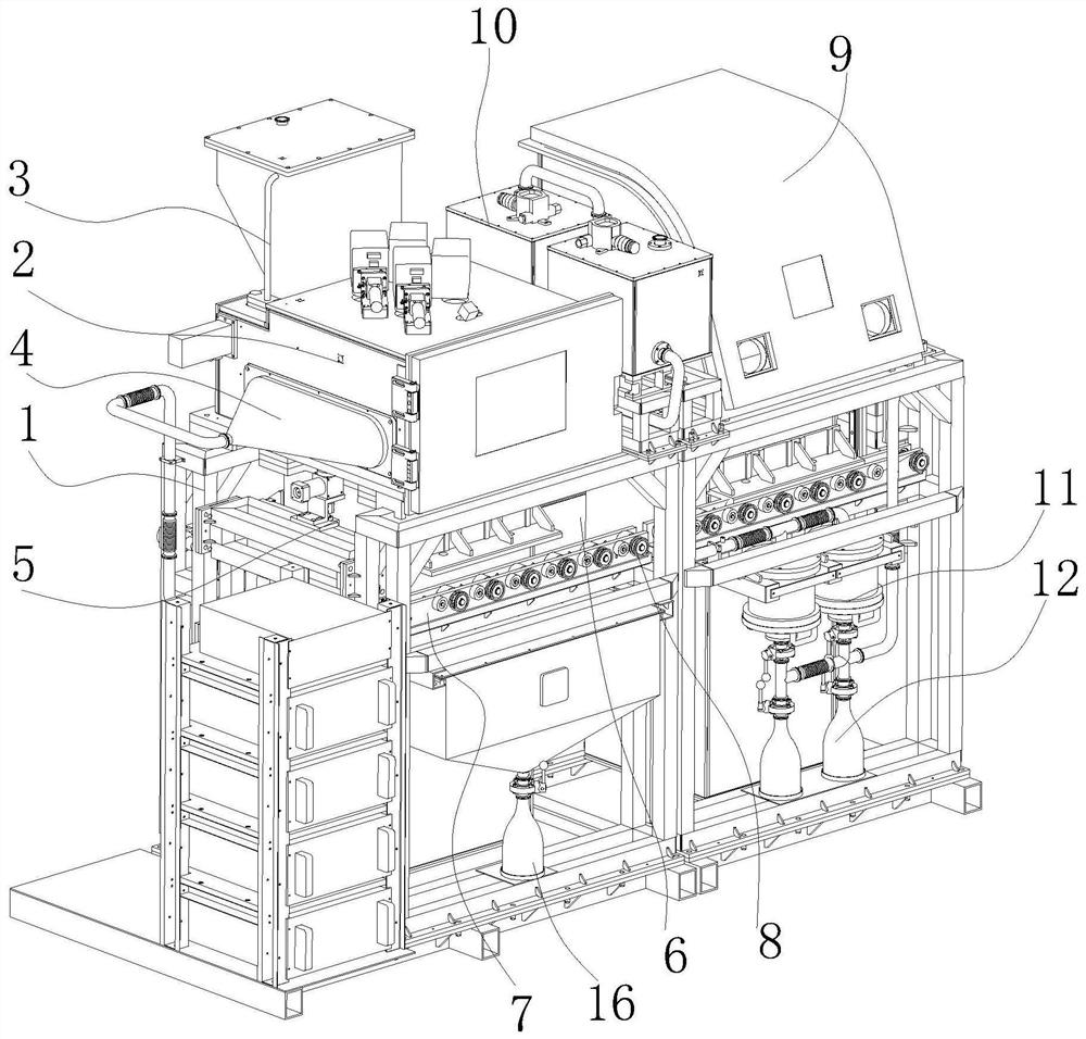
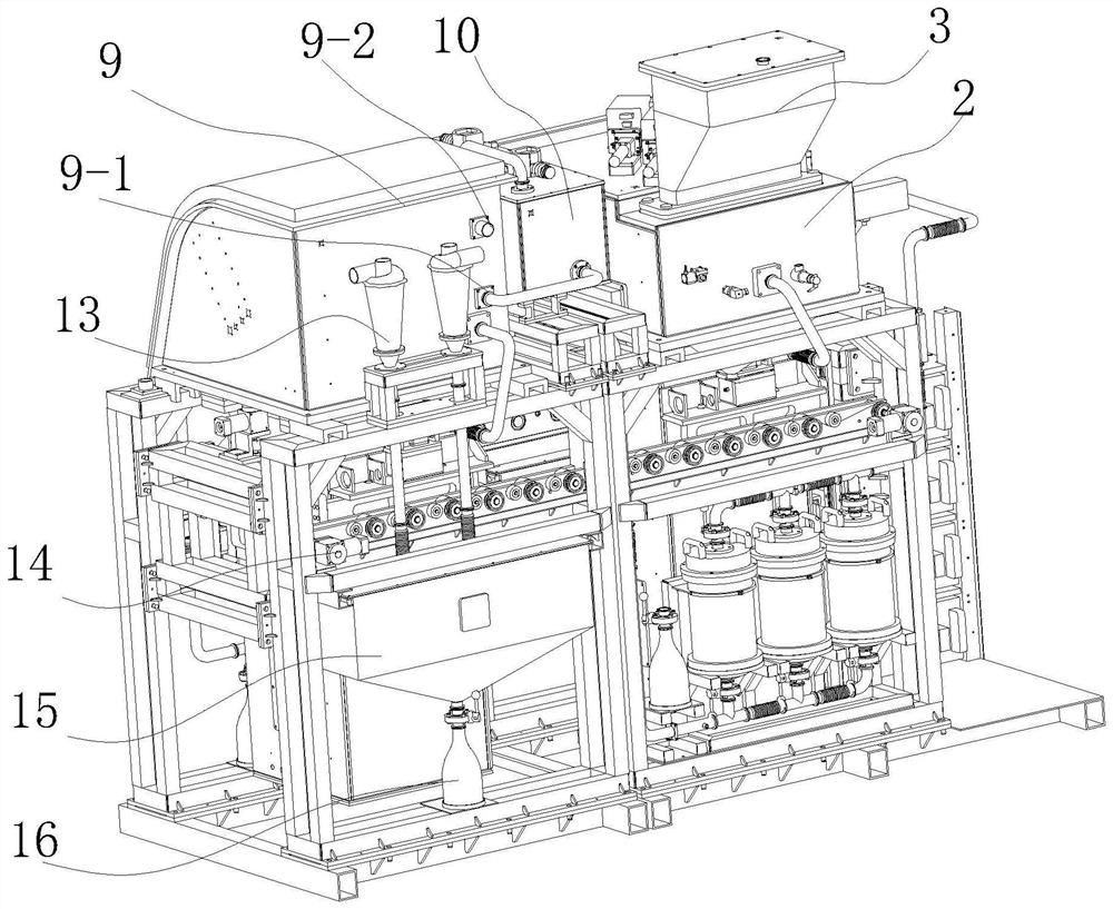
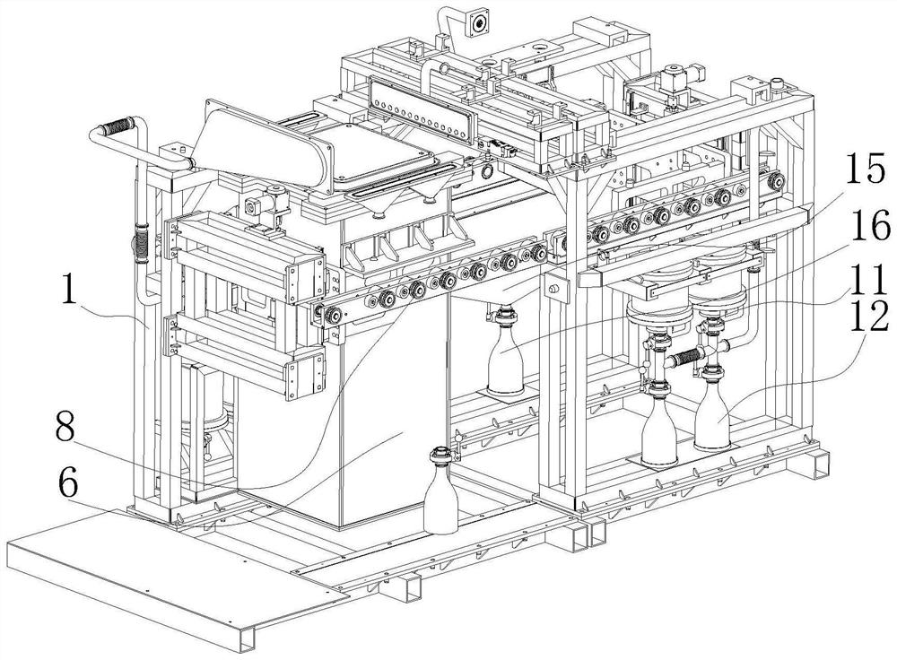
[0021] Such as Figure 1 to Figure 7 As shown, a selective area laser melting equipment with a reciprocating conveying track includes a frame 1 and a selected area laser melting equipment arranged on the frame 1, and the selected area laser melting equipment is composed of a material box arranged on the frame 1 , printing chamber 2, the print head on the printing chamber 2 and its printing platform 6. The printing platform 6 is located below the printing chamber 2 and can extend into the printing chamber 2. The material box 3 is located above the printing chamber 2 and is connected to the printing chamber. 2 connected, the frame 1 is located on the side of the printing chamber 2 and is provided with a cleaning chamber 9 for cleaning the powder on the surface of the three-dimensional model, and the lower ends of the printing chamber 2 and the cleaning chamber 9 are provided with a printing platform 6 extending The frame 1 is provided with a horizontal transmission mechanism for...

Embodiment 2

[0025] Such as Figure 1 to Figure 7As shown, a selective area laser melting equipment with a reciprocating conveying track includes a frame 1 and a selected area laser melting equipment arranged on the frame 1, and the selected area laser melting equipment is composed of a material box arranged on the frame 1 , printing chamber 2, the print head on the printing chamber 2 and its printing platform 6. The printing platform 6 is located below the printing chamber 2 and can extend into the printing chamber 2. The material box 3 is located above the printing chamber 2 and is connected to the printing chamber. 2 connected, the frame 1 is located on the side of the printing chamber 2 and is provided with a cleaning chamber 9 for cleaning the powder on the surface of the three-dimensional model, and the lower ends of the printing chamber 2 and the cleaning chamber 9 are provided with a printing platform 6 extending The frame 1 is provided with a horizontal transmission mechanism for ...


PUM


Abstract

The invention discloses selective laser melting equipment with a reciprocating type conveying rail, and belongs to the technical field of selective laser melting product production equipment. The selective laser melting equipment is composed of a material box, a printing bin and a printing platform which are arranged on a rack, wherein a cleaning bin is arranged on the rack; a horizontal conveying mechanism used for transversely conveying the printing platform is arranged on the rack, lifting supporting mechanisms used for driving the printing platform to ascend and descend are arranged at the positions, located at the two end parts of the conveying mechanism, of the rack, and a powder collecting system used for collecting powder is arranged on the rack; the cleaning bin, the powder collecting system and the conveying mechanism of the powder collecting system are arranged on the rack, so that rapid treatment of a printed three-dimensional model can be achieved, powder on the three-dimensional model can be efficiently and rapidly cleaned and collected, the treatment efficiency of a product after printing is improved, the quality of the model is guaranteed, and a good workshop environment is guaranteed.

Description

technical field [0001] The invention belongs to the technical field of laser selective fusion molding, in particular, the invention relates to a selective laser fusion equipment with a reciprocating conveying track. Background technique [0002] At present, rapid prototyping technology is developing towards direct manufacturing of metal parts. Laser selective melting is a new rapid prototyping technology that can directly form high-density and high-precision metal parts. [0003] The working principle of laser selective fusion is to discretize the designed 3D model and plan the scanning path to obtain the slice contour information that can control the laser beam scanning. Then, the computer enters the slice contour information layer by layer, and controls the laser beam through the scanning galvanometer. The metal powder is selectively melted and piled up layer by layer to form the same three-dimensional solid as the model. [0004] During the selective laser melting operat...

Claims


Application Information

Patent Timeline
Patent Type & Authority Applications(China)
IPC IPC(8): B22F3/105B33Y30/00B01D50/00
CPCB01D50/00B33Y30/00
Inventor 张成林周兵兵江华宗进陈冲锋
Owner ANHUI TUO BAO ADDITIVE MFG TECH CO LTD
Learn More