Backlight source assembling device

A technology for assembling devices and backlight sources, applied in optics, nonlinear optics, instruments, etc., can solve the problems of difficulty in realizing automatic assembly of light guide plates, low assembly efficiency, etc., so as to improve assembly efficiency and assembly quality consistency, avoid light leakage, The effect of ensuring assembly quality

Pending Publication Date: 2021-05-25
四川兆纪光电科技有限公司
View PDF0 Cites 1 Cited by
  • Summary
  • Abstract
  • Description
  • Claims
  • Application Information

AI Technical Summary

Problems solved by technology

[0003] The technical problem to be solved and the technical task proposed by the present invention are to improve the existing technology, provide a backlight assembly device, and solve the problem that the U-fold backplane is difficult to realize the automatic assembly of the light guide plate in the current technology, and the assembly efficiency is low.

Method used


Image

  • Backlight source assembling device
  • Backlight source assembling device
  • Backlight source assembling device

Examples


Embodiment 1

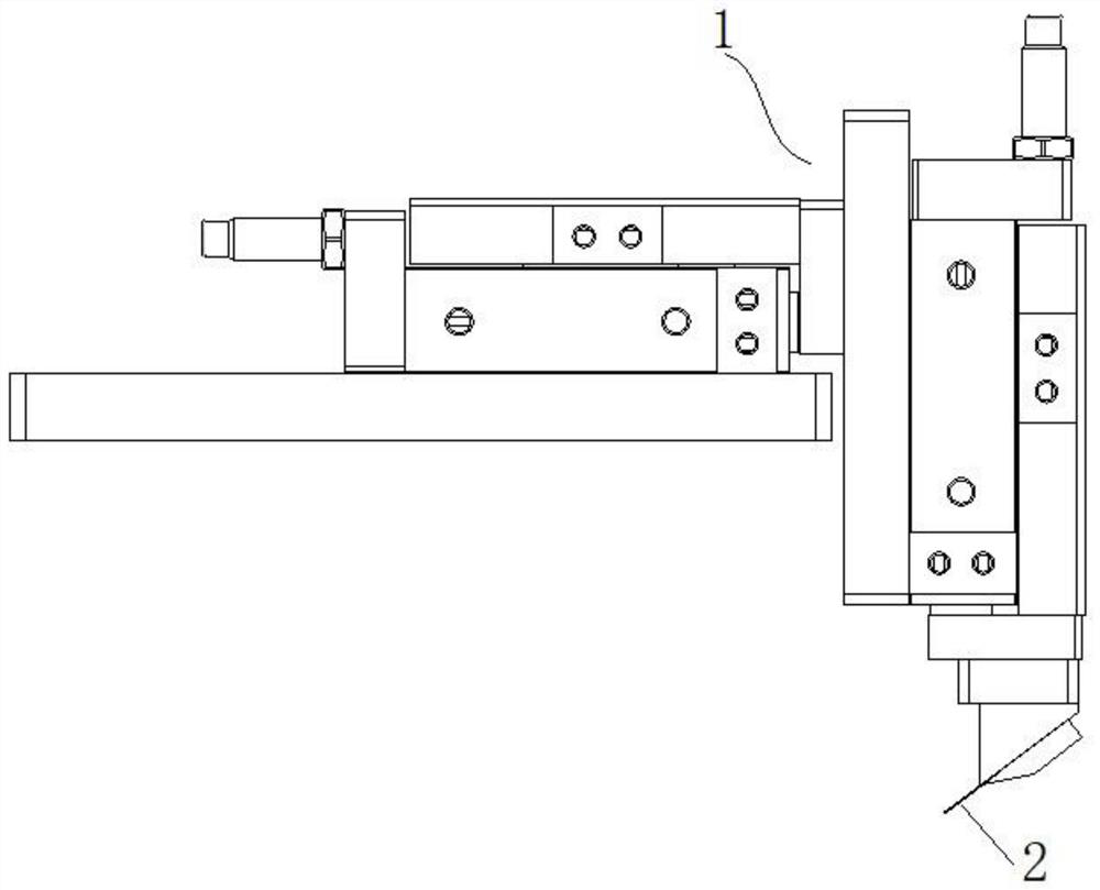
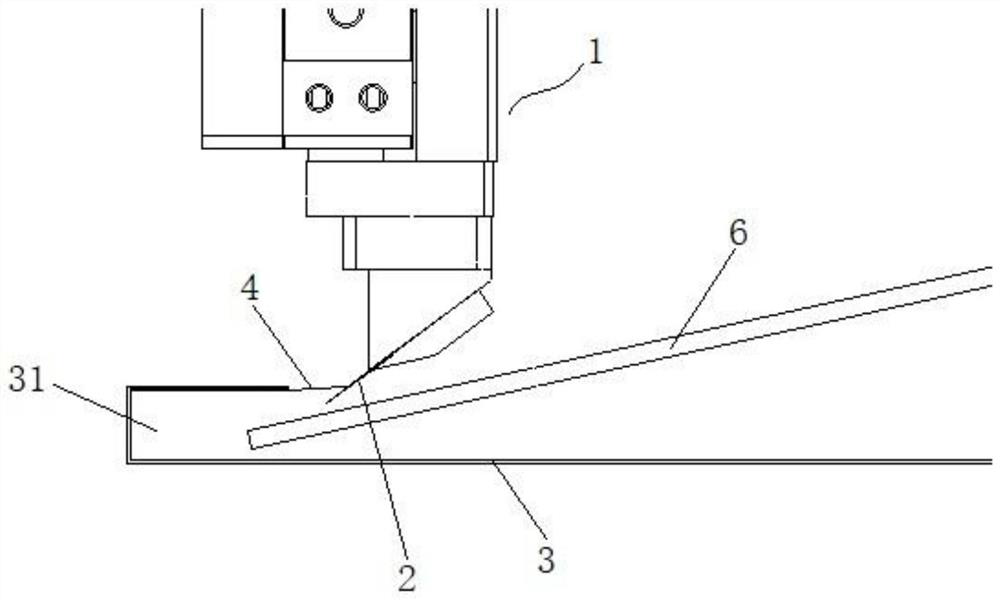
[0023] like figure 1 and figure 2 As shown, a backlight assembly device mainly includes a moving assembly 1 and a paddle 2, and the moving assembly 1 has at least the first degree of freedom of movement along the depth direction of the U-shaped groove of the U-folding backboard 3 and perpendicular to the U The second degree of freedom of movement in the direction of the surface of the folding backboard, the paddle 2 is driven to move by the moving assembly 1, and the paddle 2 is inserted into the U-shaped notch under the drive of the moving assembly 1 and connected to the U-shaped groove 31 The shading strip 4 on the side wall is in contact, and the shading strip 4 is attached to the inner side wall of the U-shaped groove, and extends out of the mouth of the U-shaped groove to achieve the purpose of shading. The surface direction of the U-fold backboard moves toward the outside of the side wall of the U-shaped groove, so that the plectrum 2 turns the light-shielding strip 4 ...

Embodiment 2

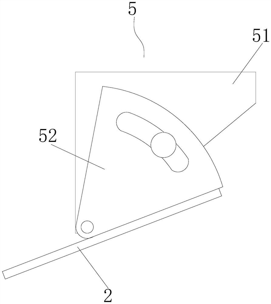
[0028] like image 3 As shown, the difference from Embodiment 1 is that the plectrum 2 is detachably connected to the mobile assembly 1, which is easy to replace and maintain, and the angle of the plectrum 2 inclined to the surface direction of the U-fold backboard 3 can be adjusted. Adjustment, so as to be able to adapt to the assembly of backlight sources of different specifications, and increase the scope of application. Specifically, the paddle 2 is connected to the moving assembly 1 through the adjusting assembly 5, and the adjusting assembly includes a base part 51 connected to the moving assembly 1 and an adjustable part 52 hinged on the base part 51, so The above-mentioned adjustable part 52 is provided with an arc-shaped chute, and the above-mentioned base part 51 is provided with a fixing hole, and the bolt passes through the chute and is locked in the fixing hole. On the adjustable part 52, the adjustable part 52 can be rotated freely by loosening the bolts. After ...


PUM


Abstract

The invention discloses a backlight source assembling device which comprises a moving assembly and a shifting piece. The moving assembly at least has a first moving freedom degree in the depth direction of a U-shaped groove of a U-folded back plate and a second moving freedom degree perpendicular to the surface direction of the U-folded back plate; the shifting piece is driven by the moving assembly to move; and the shifting piece is driven by the moving assembly so as to be inserted into an opening part of the U-shaped groove and makes contact with a shading strip on the side wall of the U-shaped groove, so that the shading strip can be turned outwards in the outer side direction of the side wall of the U-shaped groove. According to the backlight source assembling device provided by the invention, the light shielding strip is turned outwards through the shifting piece, so that a light guide plate can be smoothly inserted into the U-shaped groove of the U-folded back plate, the situation that the light shielding strip is pressed into the U-shaped groove by the light guide plate is effectively avoided, automatic assembling is achieved, traditional manual operation is replaced, and the assembling efficiency and the assembling quality consistency are improved.

Description

technical field [0001] The invention relates to the technical field of backlight production and manufacturing, in particular to a backlight assembly device. Background technique [0002] Backlight (BackLight) is a light source located behind the liquid crystal panel (LCD). Its luminous effect will directly affect the visual effect of the liquid crystal display module (LCM). The LCD panel itself does not emit light, but is illuminated by the light emitted by the backlight. Brightens the image displayed on the LCD panel. The backlight mainly includes direct-type and side-type backlight. The direct-type backlight is usually directly arranged along the surface of the liquid crystal panel and emits light toward the liquid crystal panel to illuminate the liquid crystal panel, while the side-type backlight is in the A light source emitting light along the plane direction of the liquid crystal panel is arranged on the side of the liquid crystal panel, and a light guide plate parall...

Claims


Application Information

Patent Timeline
Patent Type & Authority Applications(China)
IPC IPC(8): B23P19/04G02F1/13
CPCB23P19/04G02F1/1303
Inventor 李虹华李思升
Owner 四川兆纪光电科技有限公司
Why Eureka
Try Eureka