Working method of pipe fitting feeding and transferring mechanism

A working method and technology of pipe fittings, applied in the direction of conveyors, conveyor objects, transportation and packaging, etc., can solve problems such as unsatisfactory processing, falling off of pipe fittings, difficulty in meeting large-scale pipe fitting production and processing, etc.

Inactive Publication Date: 2021-05-25
龚文科
View PDF0 Cites 8 Cited by
  • Summary
  • Abstract
  • Description
  • Claims
  • Application Information

AI Technical Summary

Problems solved by technology

During the production and processing of pipe fittings, it is necessary to sequentially load the pipe fittings that have been processed in the previous process to enable the processing of the subsequent process. After the existing pipe fittings have been processed in the previous process, in order to continue to process the pipe Production and processing, the existing method is to manually feed the pipe fittings one by one, the labor intensity of the workers is high, and the feeding efficiency of the pipe fittings is low, making it difficult to meet the needs of large-scale pipe fitting production and processing. It is difficult to adjust the processing position of the pipe fittings during the transfer and transfer process of the pipe fittings in turn. The existing pipe fitting station adjustment mainly uses the manipulator to grab and adjust the pipe fittings, but the manipulator is used for position adjustment. , first of all, it is necessary to grab the pipe fittings. In the process of grabbing the pipe fittings, the existing manipulators often cause the pipe fittings to fall off due to poor grasping during the process of grabbing the pipe fittings, resulting in the pipe fittings not being able to be processed normally. The processing of the process makes the efficiency and quality of pipe fittings processing not guaranteed, and in the process of using the manipulator to grab the pipe fittings, the manipulator needs multiple driving mechanisms to drive continuously and independently, the driving energy consumption is high, and multiple driving mechanisms It is also very prone to failure, it is difficult to run stably for a long period of time, and it cannot guarantee that the pipe fittings can be stably grabbed and placed one by one to the required station continuously and efficiently, making it difficult for the pipe fittings to be processed efficiently and accurately
The existing pipe fittings are mainly conveyed by material pipes during the conveying process. During the feeding process of the existing pipe fittings in the vertical direction, since multiple pipe fittings are stacked together in the vertical direction, the tightness between two adjacent pipe fittings Contact, it is difficult to alternately block the pipe fittings during the downward process when conveyed by the material pipe, which makes it difficult to load the pipe fittings one by one in the vertical direction, and it is difficult to efficiently and smoothly vertically the pipe fittings during the transfer process Turning over makes it difficult to adjust the transfer station of pipe fittings conveniently and accurately, which reduces the efficiency and quality of pipe fitting processing and cannot meet the needs of processing and use

Method used


Image

  • Working method of pipe fitting feeding and transferring mechanism
  • Working method of pipe fitting feeding and transferring mechanism
  • Working method of pipe fitting feeding and transferring mechanism

Examples


Embodiment Construction

[0014] In order to further describe the present invention, a specific implementation of a pipe loading and transferring mechanism will be further described below in conjunction with the accompanying drawings. The following examples are explanations of the present invention and the present invention is not limited to the following examples.

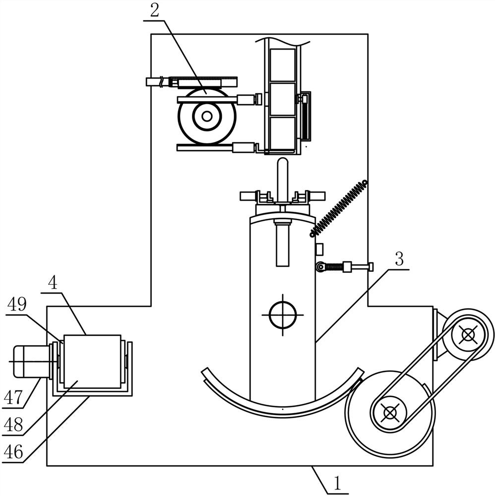
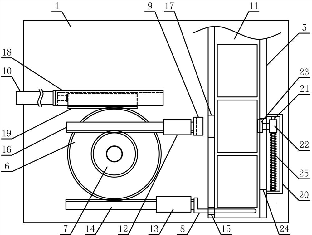
[0015] Such as figure 1 As shown, the pipe fittings feeding and transferring mechanism of the present invention includes a feeding base 1, a conduit mechanism 2, a transfer mechanism 3 and a material transfer mechanism 4, and the conduit mechanism 2 and the transfer mechanism 3 are fixedly arranged in sequence from top to bottom in the vertical direction On the side of the feeding base 1 , the material transfer mechanism 4 is horizontally arranged on the feeding base 1 on the side of the transfer mechanism 3 . Such as figure 2 As shown, the conduit mechanism 2 of the present invention includes a conduit material tube 5, a retaining gear ...


PUM


Abstract

The invention discloses a working method of a pipe fitting feeding and transferring mechanism, and belongs to the field of workpiece machining mechanical equipment. A pipe guiding mechanism and a transferring mechanism are sequentially and fixedly arranged on one side of a feeding base from top to bottom in the vertical direction, a pipe guiding material pipe is vertically arranged on one side above the feeding base, a pipe bearing mechanism and an arc-shaped connecting plate are arranged at the two ends of a reciprocating rotating plate in the rotating radial direction of the reciprocating rotating plate correspondingly, a transferring gear is in intermittent meshing connection with an arc-shaped rack, a transferring motor and the transferring gear are in transmission connection through a transferring belt, a reset tension spring is obliquely arranged between the reciprocating rotating plate and the feeding base along the pipe bearing mechanism end, a reset baffle is fixedly arranged on the portion, on one side of the reciprocating rotating plate, of the feeding base, and a conveying belt is horizontally arranged on the upper side of a conveying support. The working method is reasonable in structural design, pipe fittings can be stably guided and discharged one by one, the pipe fittings can be efficiently and accurately transferred and conveyed, the pipe fitting machining automation degree is improved, and the machining and using requirements are met.

Description

technical field [0001] The invention belongs to the field of workpiece processing machinery and equipment, and in particular relates to a working method of a pipe fitting feeding and transferring mechanism, which is mainly applied to the continuous feeding processing of pipe fittings. Background technique [0002] Pipe fittings refer to workpieces with a cylindrical structure. There are many types of pipe fittings. Different pipe fittings use different materials. The quality of the material directly determines the quality of the pipe fittings. Pipe fittings are necessary materials for construction engineering and mechanical equipment. A general term for components that play the roles of connection, control, direction change, flow diversion, sealing, support, etc. Steel pipe fittings are the most important type of pipe fittings. Steel pipe fittings are pressure-bearing pipe fittings. According to different processing techniques, steel pipe fittings can be divided into: butt w...

Claims


Application Information

Patent Timeline
Patent Type & Authority Applications(China)
IPC IPC(8): B65G47/08B65G47/248B65G47/82B65G15/32
CPCB65G15/32B65G47/08B65G47/248B65G47/82
Inventor 龚文科
Owner 龚文科
Why Eureka
Try Eureka