Rigid body positioning method for non-line-of-sight parameter estimation

A positioning method and non-line-of-sight technology, which is applied in the field of communication, can solve the problems of not considering the influence of non-line-of-sight transmission rigid body positioning performance, and difficult to meet the actual application environment.

Active Publication Date: 2021-05-25
XIAN UNIV OF POSTS & TELECOMM
View PDF5 Cites 0 Cited by
  • Summary
  • Abstract
  • Description
  • Claims
  • Application Information

AI Technical Summary

Problems solved by technology

[0005] (1) The rigid body positioning technology based on distance measurement requires strict clock synchronization, which is difficult to meet the complex practical application environment
[0006] (2) In terms of extracting wireless signal measurement parameters, the existing technology only studies the rigid body positioning in the line-of-sight environment, and does not consider the impact of non-line-of-sight transmission on the performance of rigid body positioning

Method used


Image

  • Rigid body positioning method for non-line-of-sight parameter estimation
  • Rigid body positioning method for non-line-of-sight parameter estimation
  • Rigid body positioning method for non-line-of-sight parameter estimation

Examples


Embodiment 1

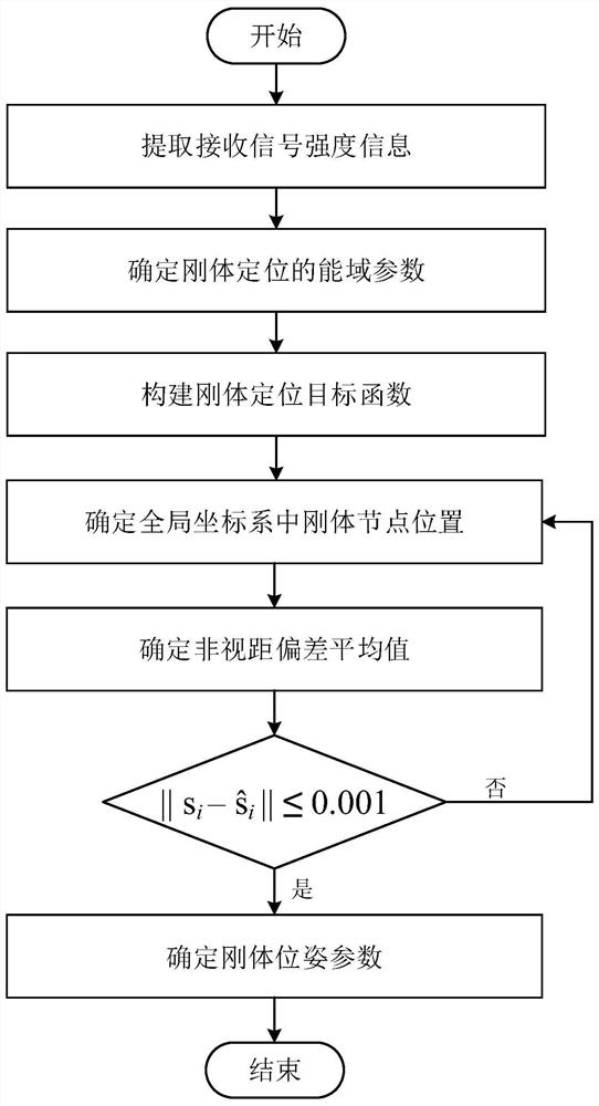
[0078] The rigid body positioning method oriented to non-line-of-sight parameter estimation in this embodiment consists of the following steps (see figure 1 ):

[0079] (1) Extract received signal strength information

[0080] According to the rigid body positioning model in the non-line-of-sight transmission environment, the anchor node is used to locate the rigid body target. The positioning method is as follows.

[0081] The m-th anchor node extracts the received signal strength information P in the energy domain of rigid body positioning from the wireless signal transmitted by the i-th rigid body node mi :

[0082]

[0083] where a m Indicates the position coordinates of the anchor node in the three-dimensional global coordinate system, a m for [x m ,y m ,z m ] T , m is 1, 2,..., M, M is the number of anchor nodes, and the value of M is a positive integer ≥ 4, and the value of M in this embodiment is 5; s i Indicates the position coordinates of the rigid body n...

Embodiment 2

[0138] In this embodiment, the rigid body positioning method for non-line-of-sight parameter estimation consists of the following steps:

[0139] (1) Extract received signal strength information

[0140] According to the rigid body positioning model in the non-line-of-sight transmission environment, the anchor node is used to locate the rigid body target. The positioning method is as follows.

[0141] The m-th anchor node extracts the received signal strength information P in the energy domain of rigid body positioning from the wireless signal transmitted by the i-th rigid body node mi :

[0142]

[0143] where a m Indicates the position coordinates of the anchor node in the three-dimensional global coordinate system, a m for [x m ,y m ,z m ] T , m is 1, 2,..., M, M is the number of anchor nodes, and the value of M is a positive integer ≥ 4, and the value of M in this embodiment is 5; s i Indicates the position coordinates of the rigid body node in the three-dimensi...

Embodiment 3

[0146] In this embodiment, the rigid body positioning method for non-line-of-sight parameter estimation consists of the following steps:

[0147] (1) Extract received signal strength information

[0148] According to the rigid body positioning model in the non-line-of-sight transmission environment, the anchor node is used to locate the rigid body target. The positioning method is as follows:

[0149] The m-th anchor node extracts the received signal strength information P in the energy domain of rigid body positioning from the wireless signal transmitted by the i-th rigid body node mi :

[0150]

[0151] where a m Indicates the position coordinates of the anchor node in the three-dimensional global coordinate system, a m for [x m ,y m ,z m ] T , m is 1, 2,..., M, M is the number of anchor nodes, and the value of M is a positive integer ≥ 4, and the value of M in this embodiment is 4; s i Indicates the position coordinates of the rigid body node in the three-dimensi...


PUM


Abstract

The invention discloses a rigid body positioning method for non-line-of-sight parameter estimation. The rigid body positioning method comprises the steps of extracting received signal strength information, determining energy domain parameters of rigid body positioning, constructing a rigid body positioning objective function, determining rigid body node positions in a global coordinate system, determining a non-line-of-sight deviation average value and determining rigid body posture parameters. According to the rigid body positioning model in the non-line-of-sight environment, the received signal strength information in a wireless signal is adopted to determine the rigid body position parameters in the non-line-of-sight environment, the clock synchronization problem needed in rigid body positioning based on distance measurement is avoided, rigid body positioning in the non-line-of-sight environment is solved, meanwhile, the non-line-of-sight deviation average value can be determined, and the robustness of rigid body positioning in the non-line-of-sight environment is ensured.

Description

technical field [0001] The invention belongs to the technical field of communication, and in particular relates to the rigid body positioning of wireless signals in a non-line-of-sight environment. Background technique [0002] In recent years, with the rapid development of sensor networks and Internet of Things technology, various smart devices and high-tech applications such as robotic systems, radar, sonar, etc. need not only to obtain the location information of the target, but also to control its posture. However, in practical application scenarios, the influence of obstacles on the performance of rigid body positioning has been very common. Due to the uncertainty of the position and motion state of the obstacle, the refraction, reflection and scattering of the positioning signal are caused, and the multipath effect occurs during the signal transmission process, resulting in an increase in the error of the signal strength measurement, which in turn makes the positioning...

Claims


Application Information

Patent Timeline
Patent Type & Authority Applications(China)
IPC IPC(8): G01S11/06H04B17/318
CPCG01S11/06H04B17/318Y02D30/70
Inventor 万鹏武魏健刘伯阳刘超文王瑾卢光跃黄琼丹姚媛媛陈煜飞
Owner XIAN UNIV OF POSTS & TELECOMM
Why Eureka
Try Eureka