Dual-core system clock synchronization method and device based on timestamp marking circuit

A technology for marking circuits and system clocks, applied in time-division multiplexing systems, electrical components, multiplexing communications, etc., can solve the problems of not being applicable to dual-core dual systems, delay jitter, and clock synchronization accuracy being greatly affected , to achieve the effect of solving clock synchronization and reducing errors

Active Publication Date: 2020-09-29
HEFEI HRG XUANYUAN INTELLIGENT TECH CO LTD
View PDF6 Cites 0 Cited by
  • Summary
  • Abstract
  • Description
  • Claims
  • Application Information

AI Technical Summary

Problems solved by technology

[0003] The network delay in the Ethernet environment is one of the main factors to be considered by the clock synchronization algorithm. Since the delay of the Ethernet may reach 50ms, it has a great impact on the accuracy of the clock synchronization, and the delay will be different due to the different loads in the network. big jitter
Therefore, the clock synchronization algorithm in Ethernet is not suitable for clock synchronization of dual-core dual systems

Method used


Image

  • Dual-core system clock synchronization method and device based on timestamp marking circuit
  • Dual-core system clock synchronization method and device based on timestamp marking circuit
  • Dual-core system clock synchronization method and device based on timestamp marking circuit

Examples


Embodiment 1

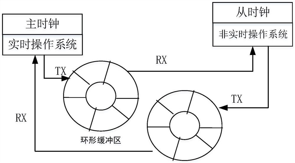
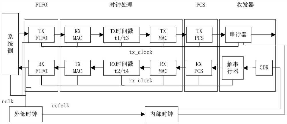
[0030] Such as figure 1 As shown, it is a schematic diagram of a dual-core system clock synchronization method based on a timestamp marking circuit disclosed in Embodiment 1 of the present invention, figure 2 A block diagram of the design implementation for obtaining timestamps inside the physical layer, figure 1 Among them, Ring buffer represents a ring buffer. Embodiment 1 of the present invention provides a dual-core system clock synchronization method based on a timestamp marking circuit. The method process is described in detail below:

[0031] The clock synchronization method is applied to AIRT-ROS real-time systems and non-real-time systems, and the time stamp marking circuit includes a local clock unit, a frequency compensation register, a synchronization message / and a delay request detection circuit, and a synchronization message / delay request time Latches, the first base address data register, the second base address data register and the time event status register...

Embodiment 2

[0052] Corresponding to Embodiment 1 of the present invention, Embodiment 2 of the present invention also provides a dual-core system clock synchronization device based on a timestamp marking circuit, which is applied to an AIRT-ROS real-time system and a non-real-time system, and the timestamp-based marking circuit includes a local Clock unit, frequency compensation register, synchronous message / and delay request detection circuit, synchronous message / delay request time latch, first base address data register, second base address data register and time event status register, first CPU Write the frequency compensation value into the frequency compensation register through the bus interface, start the local clock unit as the local clock reference; write the address of the second base address data register into the first base address data register, and write the address of the second base address data register to the second base address data register Write the address of the firs...


PUM


Abstract

The invention discloses a dual-core system clock synchronization method and device based on a timestamp marking circuit. The method is characterized in that the timestamp-based marking circuit comprises a local clock unit, a frequency compensation register, a synchronous message / and delay request detection circuit, a synchronous message / delay request time latch, a first base address data register,a second base address data register and a time event state register, firstly, a CPU writes a frequency compensation value into a frequency compensation register through a bus interface, and a local clock unit is started to serve as a local clock reference; writing an address of a second base address data register into the first base address data register, and writing an address of the first baseaddress data register into the second base address data register. The method and the device have the advantages that the timestamp is obtained by the hardware circuit at the bottom layer, the slave clock can quickly calculate and adjust the deviation with the master clock according to the transceiving timestamp, and master-slave clock synchronization is completed.

Description

technical field [0001] The invention relates to the field of clock synchronization between an AIRT-ROS real-time system and a non-real-time system, and more particularly relates to a dual-core system clock synchronization method and device based on a time stamp marking circuit. Background technique [0002] At present, the application scenarios of most clock synchronization algorithms are clock synchronization in an Ethernet environment. For example, Chinese Patent Publication No. CN103067112A discloses a clock synchronization method, device and network equipment. The device includes: at least one hardware chip, CPU and logic control Chip; the hardware chip is used to receive the first PTP event message sent by the peer device, record the first time stamp, subtract the first time stamp from the correction value in the CF field of the first PTP event message, and then send it to the CPU ; The CPU is used to send the first PTP event message to the logic control chip; the logic...

Claims


Application Information

Patent Timeline
IPC IPC(8): H04J3/06
CPCH04J3/0667H04J3/067Y02D10/00
Inventor 丁亮王飞夏科睿张亚楠于振中张韬庚彭超侯旗李小龙
Owner HEFEI HRG XUANYUAN INTELLIGENT TECH CO LTD
Why Eureka
Try Eureka