Gas reservoir identification method and device

An identification method and technology of gas reservoirs, applied in the field of petroleum exploration, can solve problems such as low Poisson's ratio, small lithological difference, multi-solution, low speed, etc., and achieve the effect of improving accuracy and reducing multi-solution

Pending Publication Date: 2021-05-25
PETROCHINA CO LTD
View PDF0 Cites 0 Cited by
  • Summary
  • Abstract
  • Description
  • Claims
  • Application Information

AI Technical Summary

Problems solved by technology

The AVO technology was proposed by Bortfeld in the 1960s, and has been popularized and applied by many scholars. However, it was later found that the AVO technology mainly analyzes the characteristics of the variation of the amplitude with the offset (that is, the amplitude information). Due to the low velocity, low density, and Low Poisson's ratio and other characteristics, and there are multiple solutions caused by small lithological differences or different fluids; the absorption and attenuation technology is mainly based on frequency information for gas layer detection. At present, many mature technologies have been derived, but their prediction resolution is low , due to the influence of lithology, there are strong multi-solutions; seismic inversion technology, especially pre-stack seismic inversion technology, has been developed for many years and has gradually matured in gas layer detection and has been popularized and applied. The requirements for well data are relatively high, and most blocks cannot meet the requirements for pre-stack inversion gas layer detection

Method used


Image

  • Gas reservoir identification method and device
  • Gas reservoir identification method and device
  • Gas reservoir identification method and device

Examples


Embodiment Construction

[0058]In order to make the objects, technical solutions, and advantages of the present invention more clearly, the technical solutions in the embodiments of the present invention will be described in the embodiment of the present invention, and the embodiments of the present invention will be described in connext of the embodiment of the present invention. It is a part of the embodiments of the present invention, not all of the embodiments. Based on the embodiments of the present invention, those of ordinary skill in the art will belong to the scope of the present invention without all other embodiments obtained without creative labor.

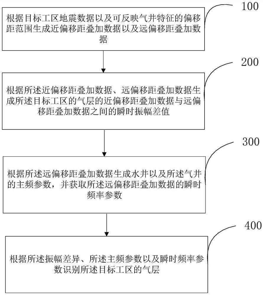
[0059]Embodiments of the present invention provide a specific embodiment of a gas layer recognition method, seefigure 1 This method specifically includes the following:

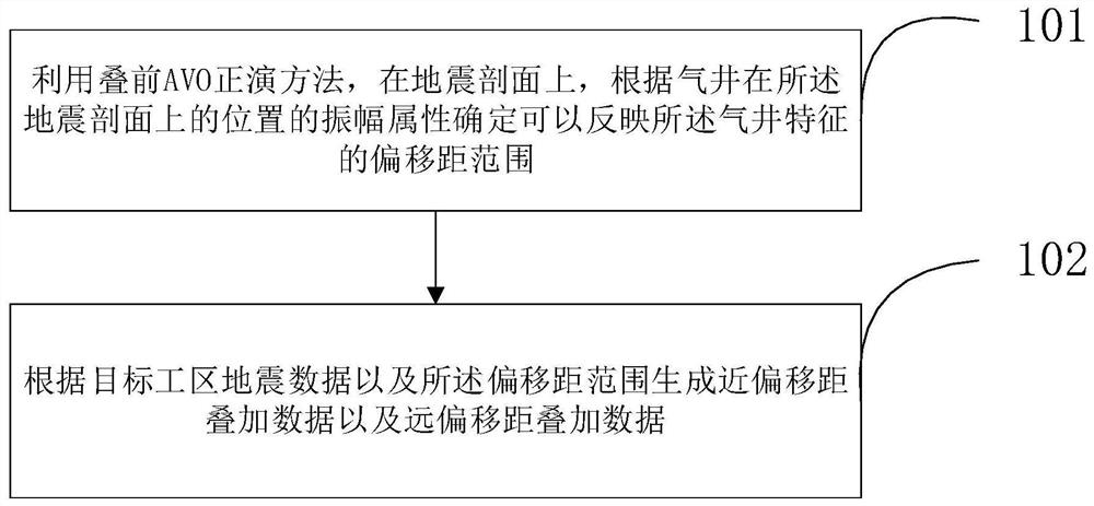
[0060]Step 100: Seismic data according to the target workspace and the offset superposition data that can reflect the air well feature and the remote offset superposition data.

[0061]When...


PUM


Abstract

The invention provides a gas reservoir identification method and device. The method comprises the following steps: generating near-offset superposition data and far-offset superposition data according to seismic data of a target work area and an offset range capable of reflecting gas well characteristics; generating an instantaneous amplitude difference value between the near-offset superposition data and the far-offset superposition data of the gas reservoir of the target work area according to the near-offset superposition data and the far-offset superposition data; generating main frequency parameters of a water well and a gas well according to the far offset superposition data, and obtaining instantaneous frequency parameters of the far offset superposition data; and identifying the gas reservoir of the target work area according to the amplitude difference, the dominant frequency parameter and the instantaneous frequency parameter. According to the gas reservoir identification method provided by the invention, the pre-stack AVO amplitude difference information and the seismic frequency information are fully utilized, the plane distribution of the gas reservoir is effectively predicted, the multiplicity of solutions of gas reservoir identification is reduced, and the precision of gas reservoir identification is improved.

Description

Technical field[0001]The present invention relates to the field of petroleum exploration, especially in the field of hydrocarbon detection in the field of geophysical exploration, and more particularly to a gas layer recognition method and apparatus.Background technique[0002]In recent years, the new proven reserves of natural gas have increased, how to improve natural gas exploration and development benefits, and ensure that natural gas production is steadily growth is an extremely complex problem. The global physical gas test is a key content that promotes efficient exploration and development of natural gas, and is one of the most important difficulties. Typical gas layers have features such as low speed, low density, low-rod stroning ratio.[0003]Currently used gas layer detection methods include AVO technology, absorption attenuation technology and seismic inversion techniques. After the introduction of Bortfeld in the 1960s, AVO technology has been promoted by many scholars, but...

Claims


Application Information

Patent Timeline
IPC IPC(8): G01V1/30G01V1/36
CPCG01V1/306G01V1/307G01V1/362G01V2210/512G01V2210/6169G01V2210/632
Inventor 李新豫包世海
Owner PETROCHINA CO LTD
Why Eureka
Try Eureka