
Lead frame plate placing and pushing-out equipment for semiconductor cutting

A lead frame and semiconductor technology, applied in semiconductor/solid-state device manufacturing, cleaning methods and utensils, cleaning methods using tools, etc. The slag adheres to the lead frame and other problems, so as to increase the conveying distance, improve the practicability and increase the stability.

Inactive Publication Date: 2021-05-25
温州斐锋生态农业科技发展有限公司
View PDF0 Cites 1 Cited by
  • Summary
  • Abstract
  • Description
  • Claims
  • Application Information

AI Technical Summary

Problems solved by technology

[0002] As the chip carrier of the inherited circuit, the lead frame acts as a bridge connecting the external wires. Most of the semiconductor integrated blocks need to use the lead frame. It is an important basic material in the electronic information industry. In order to improve production efficiency and improve material The utilization rate of semiconductors is convenient for batch processing of semiconductors. Therefore, a common lead frame is equipped with multiple chip nodes, and multiple chips are set on the chip nodes. After curing and packaging, the production of semiconductors is completed. After the production is completed , the semiconductor needs to be cut off from the lead frame, and the existing tailoring uses mechanical equipment for semiconductor tailoring, and the lead frames are placed in the tailoring device one by one continuously before cutting, although this method can realize However, since the lead frames need to be placed in the cutting device one by one by a special person, the work intensity of the operator is firstly increased, and the operator needs to place the lead frames continuously when the cutting device is running, which reduces the cutting of semiconductors. At the same time, there are no clean components on the surface of the conveyor, which will easily cause slag and other substances to adhere to the surface of the conveyor, and then easily cause slag to adhere to the lead frame, which will eventually affect subsequent processing

Method used


Image

  • Lead frame plate placing and pushing-out equipment for semiconductor cutting
  • Lead frame plate placing and pushing-out equipment for semiconductor cutting
  • Lead frame plate placing and pushing-out equipment for semiconductor cutting

Examples


Embodiment Construction

[0031] The following will clearly and completely describe the technical solutions in the embodiments of the present invention with reference to the accompanying drawings in the embodiments of the present invention. Obviously, the described embodiments are only some, not all, embodiments of the present invention. Based on the embodiments of the present invention, all other embodiments obtained by persons of ordinary skill in the art without making creative efforts belong to the protection scope of the present invention.

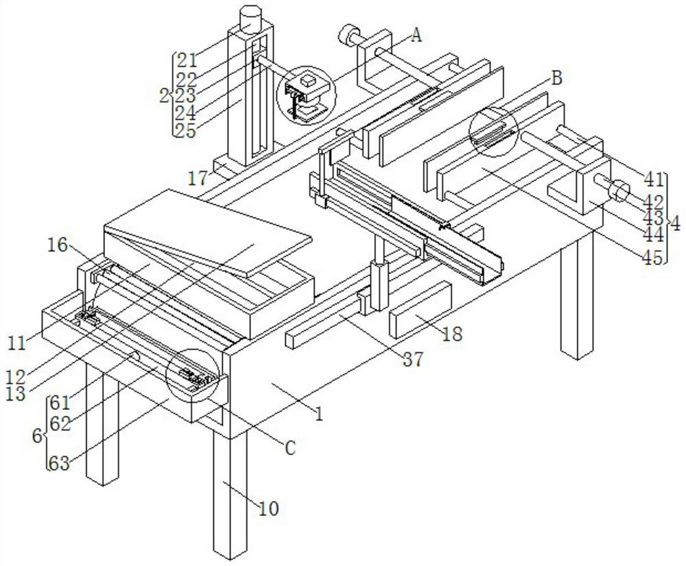
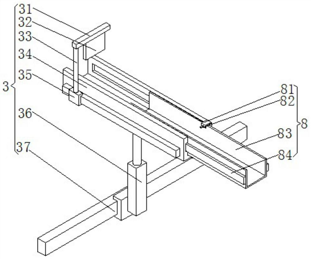
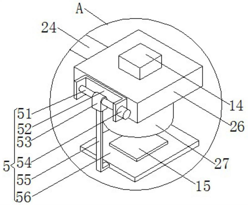
[0032] see Figure 1-5 , the present invention provides a technical solution: semiconductor tailoring lead frame plate placement and ejection equipment, including a conveyor 1, a pick-up unit 2, a placement unit 3 and a fixing plate 17;

[0033] Conveyor 1: The four corners of the bottom are provided with support legs 10, the middle part of the rear side of conveyor 1 is provided with a fixed plate 17, and the right end of conveyor 1 is provided with a limitin...


PUM


Abstract

The invention discloses lead frame plate placing and pushing-out equipment for semiconductor cutting. The lead frame plate placing and pushing-out equipment comprises a conveyor, a taking unit, a placing unit and a fixing plate. In the conveyor, supporting legs are arranged at the four corners of the bottom end of the conveyor, a fixing plate is arranged in the middle of the rear side face of the conveyor, a limiting unit is arranged at the right end of the conveyor, and a cleaning unit is arranged at the left end of the conveyor; the taking unit comprises a motor, a lead screw, a movable block, an electric telescopic rod, a fixing seat, a connecting plate and an electromagnet, the fixing seat is arranged at the top end of the fixing plate, the lead screw is rotationally connected into a groove in the front side face of the fixing seat, the motor is arranged at the top end of the fixing seat, and an output shaft of the motor is connected with the top end of the lead screw; and the movable block is in sliding connection with a groove in the front side face of the fixed seat, a screw hole in the side face of the movable block is in threaded connection with the lead screw, and the lead frame plate placing and pushing-out equipment for the semiconductor tailoring is easy to use, convenient to adjust, low in working intensity and high in production efficiency.

Description

technical field [0001] The invention relates to the technical field of lead frame boards, in particular to a device for placing and pushing out lead frame boards for semiconductor tailoring. Background technique [0002] As the chip carrier of the inherited circuit, the lead frame acts as a bridge connecting the external wires. Most of the semiconductor integrated blocks need to use the lead frame. It is an important basic material in the electronic information industry. In order to improve production efficiency and improve material The utilization rate of semiconductors is convenient for batch processing of semiconductors. Therefore, a common lead frame is equipped with multiple chip nodes, and multiple chips are set on the chip nodes. After curing and packaging, the production of semiconductors is completed. After the production is completed , the semiconductor needs to be cut off from the lead frame, and the existing tailoring uses mechanical equipment for semiconductor t...

Claims


Application Information

Patent Timeline
IPC IPC(8): H01L21/677H01L21/78B08B1/00
CPCH01L21/67742H01L21/78B08B1/12
Inventor 王震王江楠
Owner 温州斐锋生态农业科技发展有限公司
Learn More