Bus duct end connection device

A technology of terminal connection and busway, which is applied in the direction of cooling busbar devices, fully enclosed busbar devices, electrical components, etc., can solve problems such as poor heat dissipation performance, achieve the effect of reducing water ingress and enhancing waterproof performance

Active Publication Date: 2021-05-25
鼎圣集团有限公司
View PDF6 Cites 2 Cited by
  • Summary
  • Abstract
  • Description
  • Claims
  • Application Information

AI Technical Summary

Problems solved by technology

[0004] In view of the problem of poor heat dissipation in the above-mentioned existing busway end connection device, the present invention is proposed

Method used


Image

  • Bus duct end connection device
  • Bus duct end connection device
  • Bus duct end connection device

Examples


Embodiment 1

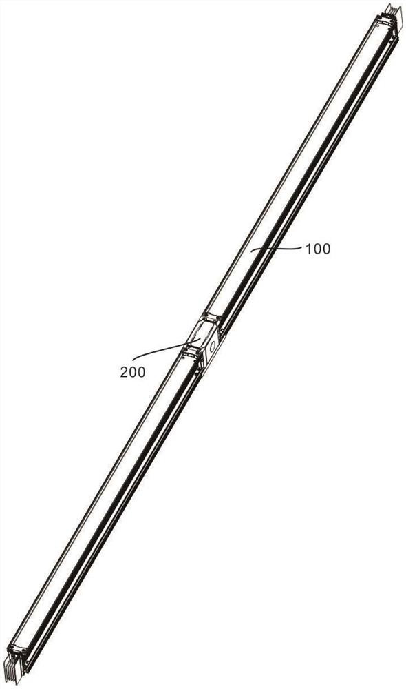
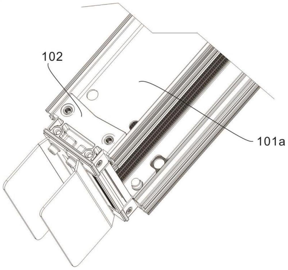
[0034] refer to Figure 1-11 , provides a schematic diagram of the overall structure of a busway end connection device, as shown in Figure 1-11 , a bus duct terminal connection device includes a connection unit 100 for connection and protection, a protection component 101 for protection and a first protective shell 101a, a connection component 102 for connection, and a clamping shell for limiting and protection 102a, the temperature control unit 200 and the temperature control component 201 for temperature control of the disconnection of the bus duct connection, the second protective shell 201a for connection and protection; Cooperate with each other to strengthen the waterproof performance of the terminals of the bus duct, thereby greatly reducing the risk of circuit burnout due to water entering the bus duct, causing power outages in commercial plazas, real estate, gymnasiums, hospitals, and industrial plants, resulting in major economic losses. In the case of loss, the he...

Embodiment 2

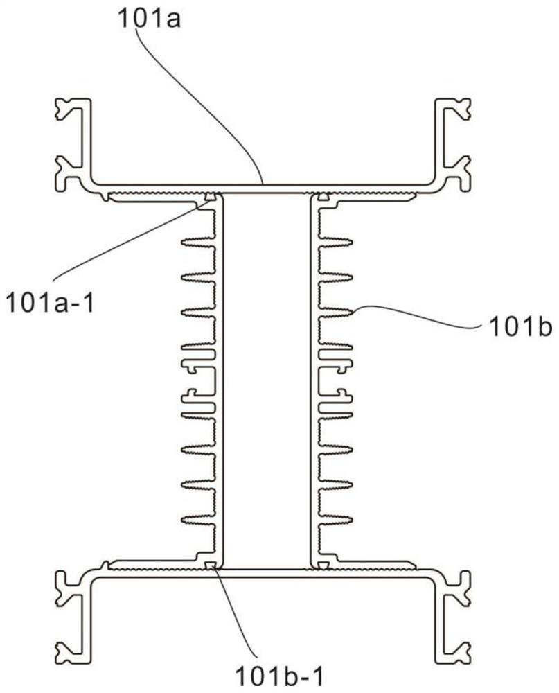
[0037] refer to Figure 2-7 , This embodiment is different from the first embodiment in that: the protective assembly 101 that plays a protective role also includes a bump 101a-1 that plays a limiting and sealing role, a heat dissipation plate 101b that plays a heat dissipation role, and plays a limiting and sealing role. The through groove 101b-1, the second through hole 101a-2 that acts as a limiter, the connection assembly 102 that acts as a connection also includes a first baffle 102b that blocks water stains, and the third through hole that acts as a limiter 102b-1, the first threaded hole 102a-1 for connection, the limit rod 102a-2 for limiting the clamping shell 102a, the first screw 102a-3 for connection, and the fixing piece for fixing and limiting 102c, the second threaded hole 102c-1 for connection, the limit groove 102c-2 for limiting the clamping shell 102a, the protective plate 102d for protection, the third threaded hole 102d-1 for connection and the second Screw...

Embodiment 3

[0043] refer to Figure 8-11 , this embodiment is different from the above embodiments in that: the temperature control component 201 for controlling the temperature of the disconnection of the busway connection includes a heat conduction layer 201b for transferring heat, a phase change material 201c for absorbing and releasing heat, and a busbar The isolation layer 201d that protects the end of the groove, the fixing assembly 202 that plays a fixing role, the limiting plate 202a that plays a limiting role, the threaded pipe 202b and the limiting screw 202c, the adjusting nut 202d that plays a fixing and adjusting role, and the circuit The connected terminal 202e absorbs the heat generated by the circuit operation through the heat conduction layer 201b in the temperature control component 201, so as to control the temperature of the circuit operation within the normal range, and avoid the busbar terminal often being damaged due to poor heat dissipation performance. Leading to ...


PUM


Abstract

A bus duct end connection device disclosed by the present invention comprises a connection unit and a temperature control unit. The connection unit comprises a protection assembly and connection assemblies located at the two ends of the protection assembly, the protection assembly comprises symmetrically arranged first protection shells, and the connection assemblies comprise clamping shells located at the two ends of the first protection shells; and the temperature control unit comprises a temperature control assembly located between the connecting assemblies, and the temperature control assembly comprises a second protective shell fixed to the clamping shell through screws. Heat generated by circuit operation is absorbed through a temperature control assembly in the temperature control unit, so that the temperature of circuit operation is controlled to be within a normal range, and the situation that a bus duct end often causes circuit burnout due to poor heat dissipation performance, power failure of a large commercial plaza, a building, a gymnasium, a hospital, an industrial factory building and the like is caused, and economic loss is caused.

Description

technical field [0001] The invention relates to the technical field of bus duct protection, in particular to a bus duct end connection device. Background technique [0002] The busway adopts a typical "sandwich" structure, the conductors are closely arranged, the structure is compact, and the space occupation is smaller. It is a safe and reliable power distribution system, suitable for three-phase three-wire system, three-phase four-wire system, three-phase five-wire system (The shell is made of PE, and the cross-section of the three-phase five-wire system is half of the phase wire). Frequency 50 / 60Hz, rated working voltage up to 690V, rated insulation voltage up to 1000V, rated working current 250A-6300A power supply system; the highest protection level can reach IP66, the protection level of the socket can reach IP65; the busway can be widely used in large-scale commercial plazas, real estate, gymnasiums, hospitals, industrial plants and other projects, as a high-efficienc...

Claims


Application Information

Patent Timeline
Patent Type & Authority Applications(China)
IPC IPC(8): H02G5/06H02G5/10H02G3/06
CPCH02G5/06H02G5/10H02G3/06
Inventor 张梓康李立军
Owner 鼎圣集团有限公司
Why Eureka
Try Eureka