
Computer network monitoring device

A computer network and monitoring device technology, applied in the field of computer network monitoring devices, can solve problems such as dust accumulation, air inlet blockage, camera lens fogging, etc., and achieve the effects of prolonging service life, improving safety performance, and avoiding dust blockage

Inactive Publication Date: 2021-05-25
长春科技学院
View PDF0 Cites 0 Cited by
  • Summary
  • Abstract
  • Description
  • Claims
  • Application Information

AI Technical Summary

Problems solved by technology

[0003] During the use of the computer network monitoring device, the internal electrical components will generate high temperature. When the traditional computer network monitoring equipment dissipates heat, the air inlet will accumulate a lot of dust during the long-term suction work, causing the air inlet to be blocked. At the same time, when the internal temperature rises, the lens of the camera may fog up, which will affect the normal use of monitoring. Therefore, we propose a computer network monitoring device to solve the above problems

Method used


Image

  • Computer network monitoring device
  • Computer network monitoring device
  • Computer network monitoring device

Examples


Embodiment Construction

[0027] The following will clearly and completely describe the technical solutions in the embodiments of the present invention with reference to the accompanying drawings in the embodiments of the present invention. Obviously, the described embodiments are only some, not all, embodiments of the present invention.

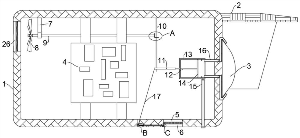
[0028] refer to Figure 1-6 , a computer network monitoring device, comprising a housing 1, a baffle 2, and a network monitoring system;

[0029] The network monitoring system includes a network control center, a video monitoring module, an image recognition module, a data storage module, a data sending module, a data receiving module, a data display module, a power switch module, a fan control module, and a data clearing module;

[0030] The output end of the network control center is electrically connected to the input end of the power switch module, the output end of the network control center module is electrically connected to the input end of the fan control mo...


PUM


Abstract

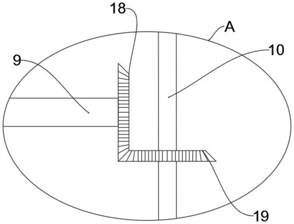
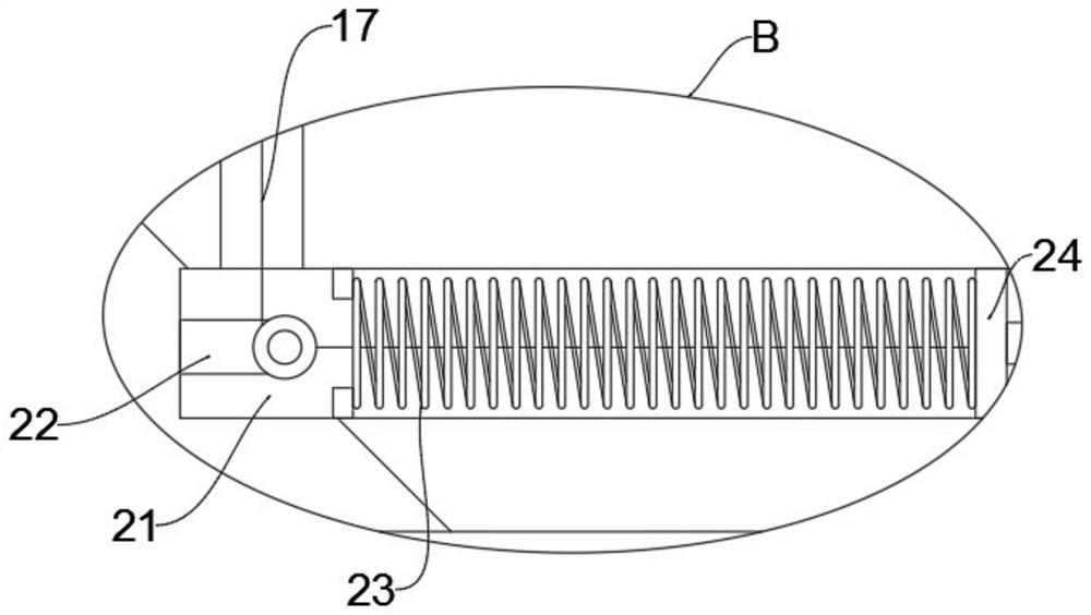
The invention discloses a computer network monitoring device which comprises a shell, a baffle and a network monitoring system, and the network monitoring system comprises a network control center, a video monitoring module, an image recognition module, a data storage module, a data sending module, a data receiving module, a data display module, a power switch module, a fan control module and a data clearing module. A fan rotates, a movable rotating shaft rotates, a first gear drives a second gear to rotate, a transmission rod rotates, a special-shaped gear drives a reciprocating plate to do reciprocating motion, then a reciprocating rod moves leftwards, an extrusion plate moves leftwards, and air is sucked through the interior of a one-way air inlet pipe. When a reciprocating lever moves to the right, air in the extrusion groove is blown to the surface of the camera through the one-way air outlet pipe, mist rising on the lens due to internal high temperature is blown away, the situation that monitoring work is affected due to the fact that mist is accumulated on the surface of the camera is avoided, and stable use of work is ensured.

Description

technical field [0001] The invention relates to the technical field of network monitoring, in particular to a computer network monitoring device. Background technique [0002] The monitoring system is one of the most widely used systems in the security system. The most suitable construction site monitoring system on the market is a handheld video communication device. Video monitoring is now the mainstream. From the earliest analog monitoring to the fiery digital monitoring in the past few years, it is now in the ascendant. Network video surveillance has undergone earth-shaking changes. Now that IP technology is gradually unifying the world, it is necessary for us to re-understand the development history of video surveillance systems. From a technical point of view, the development of video surveillance systems is divided into the first generation of analog video surveillance systems (CCTV), From the second generation of digital video surveillance system (DVR) based on "PC+m...

Claims


Application Information

Patent Timeline
IPC IPC(8): H04N7/18B08B1/00G03B17/55
CPCH04N7/18G03B17/55B08B1/165
Inventor 陈静李赫宇卢健刘晓辉张井柱王婷婷李雪梅李阳刘燚
Owner 长春科技学院
Learn More