Power generation denitration equipment

A technology of equipment and electric power, which is applied in the field of out-of-stock equipment for power generation, can solve problems such as reducing life, impact damage, and affecting out-of-stock efficiency, and achieve the effects of reducing out-of-stock efficiency, preventing pollution and blockage, and optimizing the evaporation and transportation process

Inactive Publication Date: 2020-06-19
胡梦茹
View PDF0 Cites 1 Cited by
  • Summary
  • Abstract
  • Description
  • Claims
  • Application Information

AI Technical Summary

Problems solved by technology

[0002] At present, the exhaust gas emitted by burning fuel in thermal power generation contains a large amount of NOx, and the reactant of NOx is an important substance that causes air pollution. Therefore, the elimination of exhaust gas is the top priority in environmental protection work. Two process methods: SCR catalyst destocking and SCAN catalyst destocking process. In terms of destocking efficiency, SCR catalyst destocking is the most efficient method, but the cost is high. The current SCR catalyst destocking has the following disadvantages: 1. Ammonia gas The transportation adopts a separate set of transportation technology. Usually, ammonia water is atomized through the evaporator and then diluted through the air mixer, and then discharged through the nozzle in the flue and enters the catalyst together with the flue gas. The structure is complex and the cost is high. 2. Smoke Na, Ga and Si in the gas will pollute the catalyst and cause the honeycomb catalyst to be polluted, reducing the service life. At the same time, the caustic soda formed by Na and Ga will block the honeycomb catalyst and affect the off-stock efficiency. 3. The flue gas contains Flying dust is easy to cause impact damage to the honeycomb catalyst, and it will also block the honeycomb catalyst. Therefore, the invention provides a power generation out-of-stock equipment

Method used


Image

  • Power generation denitration equipment
  • Power generation denitration equipment
  • Power generation denitration equipment

Examples


Embodiment approach

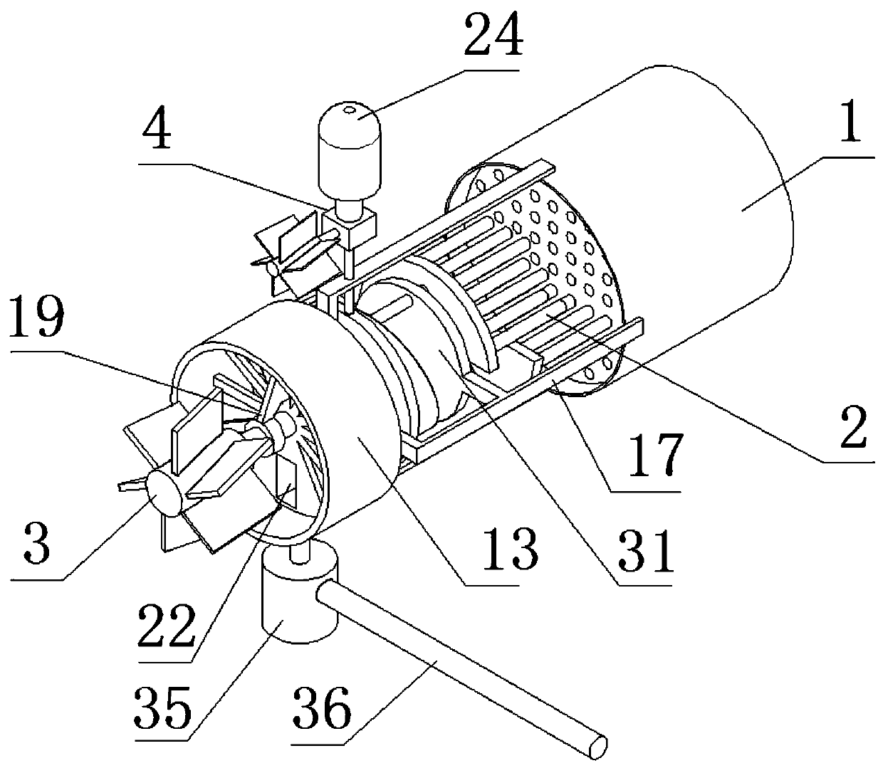
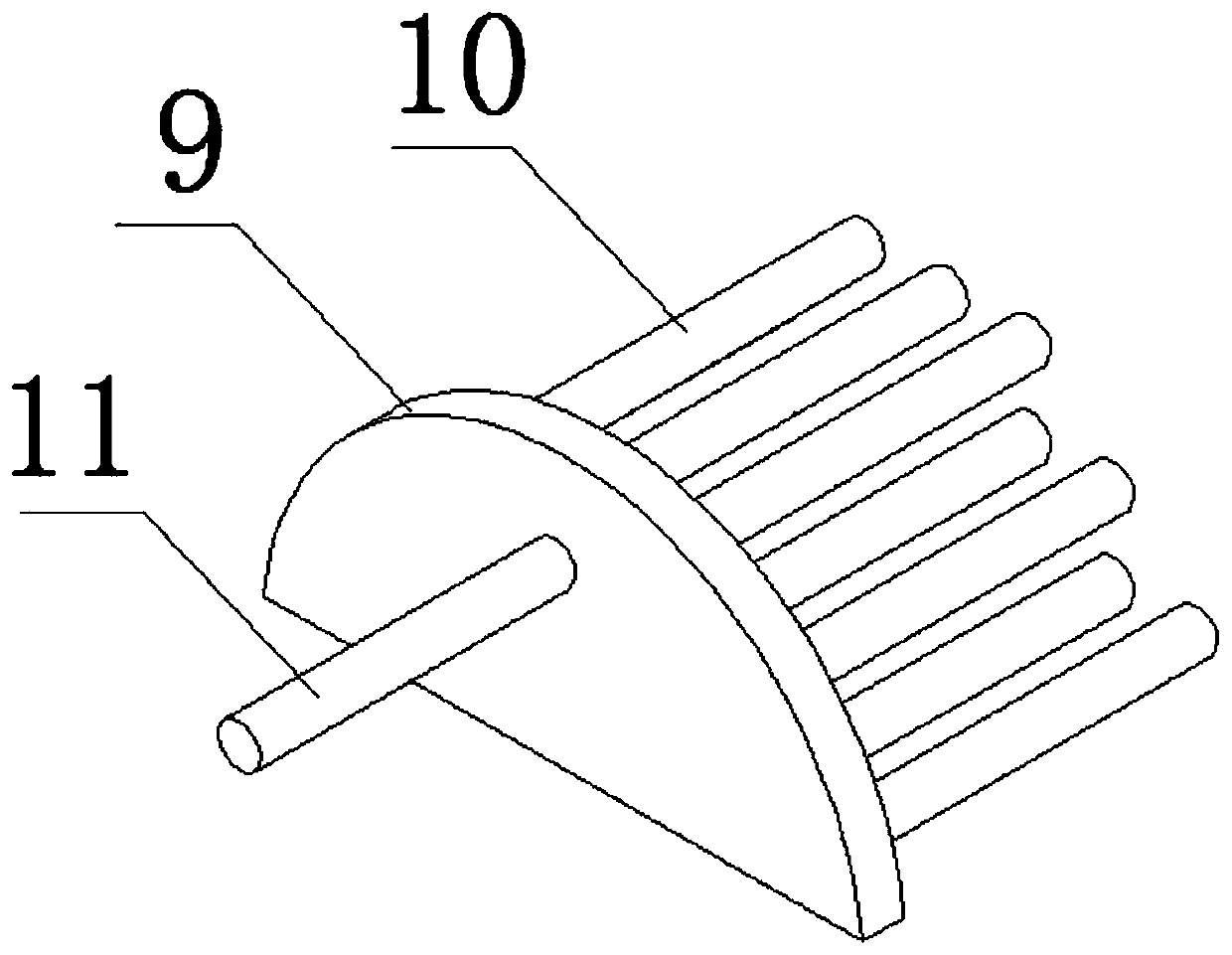
[0027] As a preferred embodiment of the present invention, the injection pipe 10 is provided with injection holes.

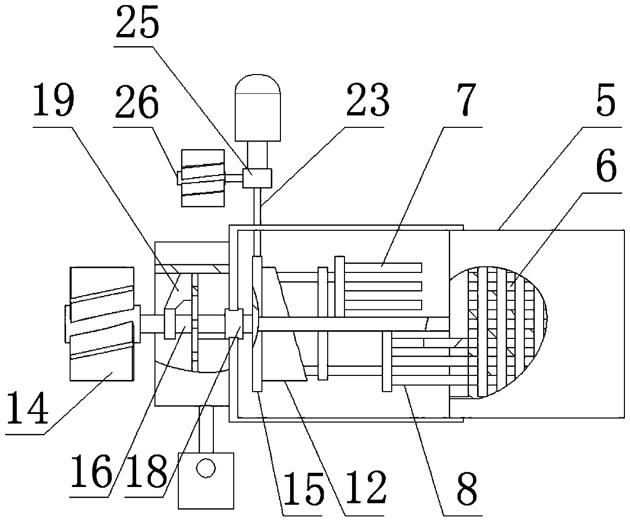
[0028] As a preferred embodiment of the present invention, the upper jet pipe group 7 and the lower jet pipe group 8 are of the same size and specification.

[0029] As a preferred embodiment of the present invention, an air injection hole is provided in the ventilation chute, and a touch exhaust valve is provided in the air injection hole, and the slider 32 and the ventilation chute form a sliding pair.

[0030] As a preferred embodiment of the present invention, the semicircular distribution plate 9 is provided with a distribution cavity 33 .

[0031] As a preferred embodiment of the present invention, the scraper 20 and the dust collection bar constitute a sliding pair.

[0032] As a preferred embodiment of the present invention, the scraper 20 is provided with a dust collection brush 34 .

[0033] As a preferred embodiment of the present invention, a dust ...


PUM


Abstract

The invention discloses power generation denitration equipment, which comprises an SCR reactor catalyst, a composite dense ammonia gas ejection pipe group, a rotary flying dust collector and an ammonia gas conveying group, wherein the SCR reactor catalyst comprises a fixing sleeve and a honeycomb catalyst, the honeycomb catalyst is arranged in the fixing sleeve in a sleeving manner, the compositedense ammonia gas ejection pipe group comprises an upper gas ejection pipe group and a lower gas ejection pipe group, the upper gas ejection pipe group comprises a semicircular flow dividing disc, aninjection pipe and a conveying pipe, the injection pipe is arranged on one side of the semicircular flow dividing disc, the conveying pipe is arranged on the other side of the semicircular flow dividing disc, and the rotary flying dust collector comprises a rotary thrust disc, a flying dust collector, an impeller set, an ammonia water turnover disc and a dust scraper. According to the invention, nanoparticle convolution evaporation effect is adopted, and evaporated ammonia gas is directly fed into a honeycomb catalyst through an injection pipe, so that the traditional evaporation conveying process flow for conveying ammonia gas is optimized.

Description

technical field [0001] The invention relates to the technical field of thermal power generation, in particular to an out-of-stock equipment for electric power generation. Background technique [0002] At present, the exhaust gas emitted by burning fuel in thermal power generation contains a large amount of NOx, and the reactant of NOx is an important substance that causes air pollution. Therefore, the elimination of exhaust gas is the top priority in environmental protection work. Two process methods: SCR catalyst destocking and SCAN catalyst destocking process. In terms of destocking efficiency, SCR catalyst destocking is the most efficient method, but the cost is high. The current SCR catalyst destocking has the following disadvantages: 1. Ammonia gas The transportation adopts a separate set of transportation technology. Usually, ammonia water is atomized through the evaporator and then diluted through the air mixer, and then discharged through the nozzle in the flue and e...

Claims


Application Information

Patent Timeline
Patent Type & Authority Applications(China)
IPC IPC(8): B01D53/86B01D53/56
CPCB01D53/8631B01D2251/2062
Inventor 胡梦茹
Owner 胡梦茹
Why Eureka
Try Eureka