
Flue gas treatment system

A flue gas treatment system and flue gas technology, applied in the field of gas purification, can solve problems such as the hazards of flue gas emissions

Pending Publication Date: 2021-05-28
BEIJING SPC ENVIRONMENT PROTECTION TECH
View PDF0 Cites 0 Cited by
  • Summary
  • Abstract
  • Description
  • Claims
  • Application Information

AI Technical Summary

Problems solved by technology

[0003] In order to solve all or part of the above problems, the purpose of the present invention is to provide a flue gas treatment system to improve the reaction efficiency of flue gas denitrification reaction, thereby reducing the risk of flue gas emission harmful to the environment

Method used


Image

  • Flue gas treatment system

Examples


Embodiment Construction

[0018] The present invention will be further described below in conjunction with accompanying drawing.

[0019] In this application, terms such as "installation", "connection", "connection" and "fixation" should be interpreted in a broad sense, for example, it can be a fixed connection or a detachable connection, unless otherwise clearly specified and limited. , or integrated; it can be mechanically connected or electrically connected; it can be directly connected or indirectly connected through an intermediary, and it can be the internal communication of two components or the interaction relationship between two components. Those of ordinary skill in the art can understand the specific meanings of the above terms in the present invention according to specific situations.

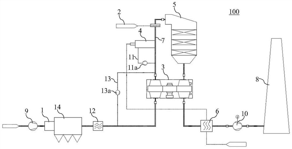
[0020] figure 1 A flue gas treatment system according to an embodiment of the present invention is schematically shown. The flue gas treatment system 100 of the embodiment of the present invention is pref...


PUM


Abstract

The invention relates to a flue gas treatment system. The flue gas treatment system comprises an ammonia injection device, a first dividing wall type heat exchanger, a flue gas heater and a denitration reactor, wherein a heat absorption side flue gas inlet of the first dividing wall type heat exchanger is used for receiving flue gas, a heat absorption side flue gas outlet of the first dividing wall type heat exchanger is connected with a flue gas inlet of the ammonia injection device, and a flue gas outlet of the ammonia injection device is connected with a flue gas inlet of the denitration reactor; a flue gas outlet of the denitration reactor is connected with a heat release side flue gas inlet of the first dividing wall type heat exchanger, a heat release side flue gas outlet of the first dividing wall type heat exchanger is connected with a chimney, and treated flue gas is discharged through the chimney; and the flue gas heater is arranged between the first dividing wall type heat exchanger and the ammonia injection device and can heat flue gas which passes through the first dividing wall type heat exchanger and is less than 280 DEG C to 280-300 DEG C. The flue gas treatment system disclosed by the invention is used for improving the reaction efficiency of the denitration reaction of the flue gas treatment system when the flue gas temperature is relatively low, and the risk that the discharged flue gas harms the environment can be reduced.

Description

technical field [0001] The invention belongs to the technical field of gas purification, and in particular relates to a flue gas treatment system. Background technique [0002] With the development of the national economy and the improvement of people's living standards, people pay more and more attention to environmental issues. Many production enterprises discharge a large amount of flue gas including pollutants into the external environment, causing serious pollution to the environment. Flue gas treatment has become an important environmental protection measure. In the existing technology, the flue gas that needs to be denitrated often does not reach the temperature suitable for the denitrification reaction (that is, 280°C to 300°C). In order to improve the reaction efficiency of the denitrification reaction, the existing flue gas treatment system mainly includes ammonia injection. device, a partitioned heat exchanger, and a denitrification reactor that can implement sel...

Claims


Application Information

Patent Timeline
IPC IPC(8): B01D53/90B01D53/56F23J15/08
CPCB01D53/005B01D53/8631B01D53/90B01D2251/2062B01D2258/0283F23J15/08
Inventor 高现尧殷旭武国伟霍兴甲刘晶王柏森梁凤李梅高小红李蕾
Owner BEIJING SPC ENVIRONMENT PROTECTION TECH
Learn More