
A split-guided inertial cyclone separator

A cyclone separator and split-flow technology, which is applied in the field of two-phase separation treatment technology, can solve the problems of poor separation effect of small particle size dispersed phase, poor separation effect of small particle size droplets, and limitation of cyclone separation efficiency, etc. Achieve considerable promotion and application prospects, reduce turbulent flow, and improve overall efficiency

Active Publication Date: 2021-11-23
NORTHEAST GASOLINEEUM UNIV
View PDF13 Cites 0 Cited by
  • Summary
  • Abstract
  • Description
  • Claims
  • Application Information

AI Technical Summary

Problems solved by technology

For the cyclone separation technology, the cyclone separation method is difficult to separate the dispersed phase with small size. The particle size distribution of the dispersed phase is one of the important factors that determine the efficiency of the cyclone separation. In practical applications, large The separation effect of particle size droplets is good, and the separation effect of small particle size droplets is poor. These droplets with small particle size directly follow the continuous phase and flow out from the continuous phase outlet without separation, which has a certain impact on the separation effect.
[0003] The cyclone separation system or device has been applied in related industries in my country. The invention patents for the cyclone separation system or device, such as (CN201310063840.8, CN201610184831.8, CN201610157839.5, CN201610126588.4, CN201620006971.1, CN201520974246.9), etc., but the above inventions all have the disadvantage of poor separation effect on small particle size dispersed phases when separating the liquid flow, which limits the improvement of the separation efficiency of the cyclone

Method used


Image

  • A split-guided inertial cyclone separator
  • A split-guided inertial cyclone separator
  • A split-guided inertial cyclone separator

Examples


Embodiment Construction

[0024] The present invention will be further described below in conjunction with accompanying drawing:

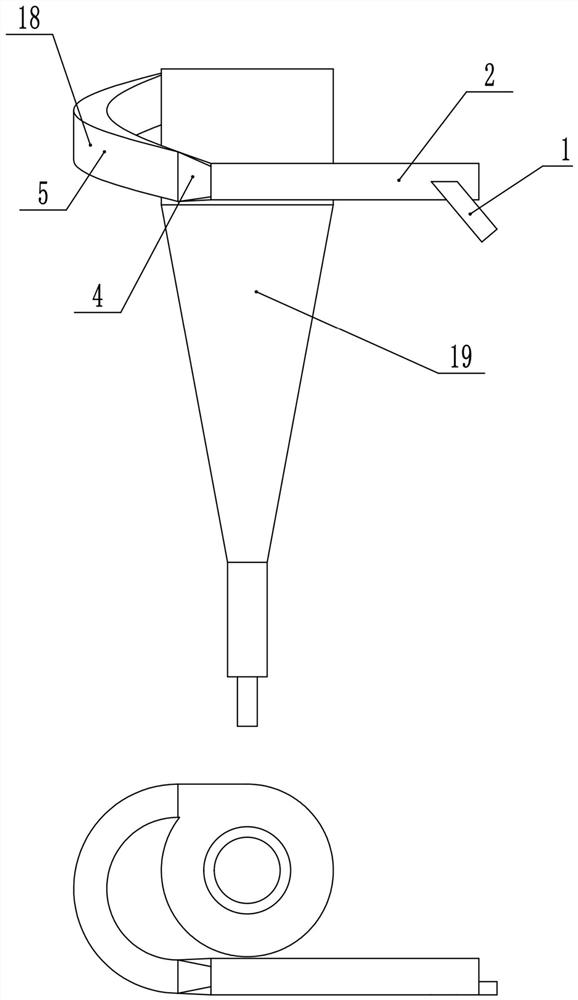
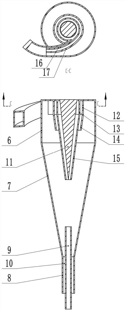
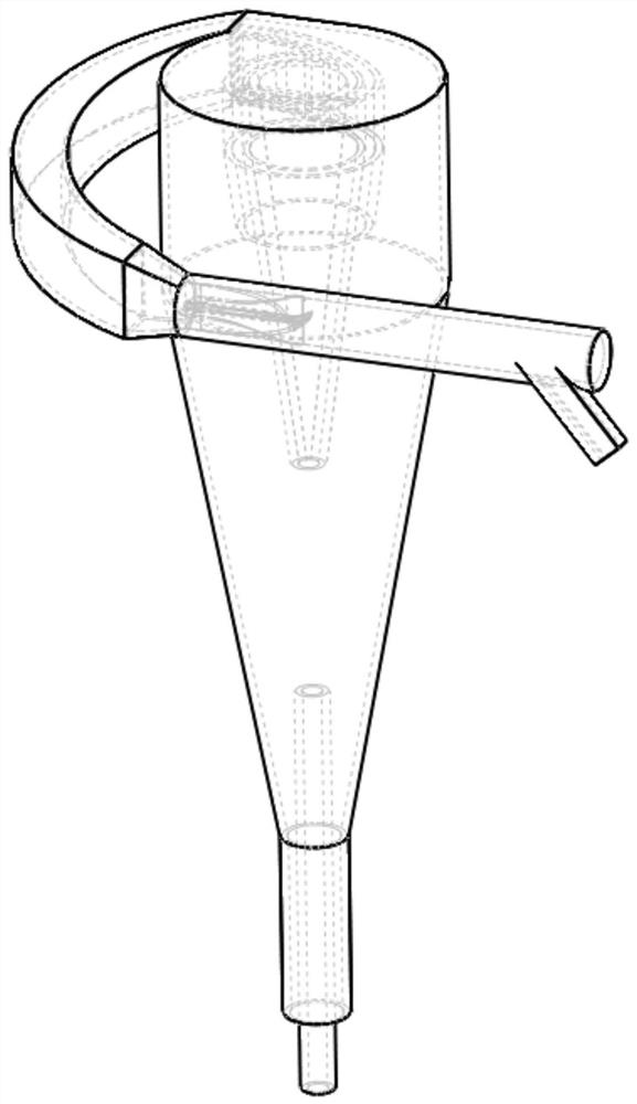
[0025] A split-guided inertial cyclone separator, comprising a coalescing split-type inlet 18 and a cylinder 19, characterized in that:

[0026] The coalescing and splitting inlet 18 is composed of an inclined tangential inlet 1, a coalescing pipe 2, a guide body 3, a conversion pipe 4, and a diverting guide pipe 5. The coalescing pipe 2 is a hollow cylinder, along which the coalescing The outer wall of the coalescing pipe 2 is inclined and tangentially connected to a tangential inlet 1. The tangential inlet 1 connected obliquely can make the fluid generate a tangential velocity in the coalescing pipe 2, so that the oil droplets rotate and coalesce, and the tangential inlet is due to It is inclined, which can share part of the tangential force in the axial direction, and avoid the flow field disorder caused by excessive tangential velocity. The conversion tube 4 is a gradu...


PUM


Abstract

A split-guided inertial cyclone separator, comprising a coalescing split-flow inlet and a barrel; the coalescing split-flow inlet includes a tangential inlet, a coalescing pipe, a guide body, a conversion pipe, and a split-flow guiding pipe; the barrel The body is composed of a swirl section, a cone section, and an underflow section with the same central axis from top to bottom. The present invention can separate and stratify the continuous phase, the discrete phase with a large particle size and the discrete phase with a small particle size under the action of inertia through the split-guided inlet, and guide three different fluids to the cyclone through the inner layer and the outer layer guide plate At different positions inside, the discrete phases with different particle sizes are finely separated. The cyclone can achieve high separation efficiency for dispersed phases with large and small particle sizes, and it has outstanding advantages such as small equipment volume and targeted diversion and guidance for droplets of different sizes to complete efficient separation.

Description

technical field [0001] The invention relates to a diversion-guided inertial cyclone separator, which is mainly used in the fields of petroleum, chemical industry, environmental protection and the like, and is specifically a two-phase separation treatment technology. Background technique [0002] At present, the separation methods for two-phase immiscible media mainly include gravity sedimentation method, electric field separation method, chemical adsorption separation method and filtration separation method. Cyclone separation technology is widely used in petroleum, chemical industry and other fields due to its fast separation speed and small equipment. Environmental protection and other fields. For the cyclone separation technology, the cyclone separation method is difficult to separate the dispersed phase with small size. The particle size distribution of the dispersed phase is one of the important factors that determine the efficiency of the cyclone separation. In practic...

Claims


Application Information

Patent Timeline
Patent Type & Authority Patents(China)
IPC IPC(8): B04C3/06
CPCB04C3/06
Inventor 赵立新王思淇张爽刘琳徐保蕊邢雷
Owner NORTHEAST GASOLINEEUM UNIV
Learn More