Automatic cleaning device for textile dye barrel

An automatic cleaning and dye bucket technology, which is applied to cleaning hollow objects, drying gas arrangement, cleaning methods and utensils, etc., can solve the problems of low cleaning efficiency of textile dye buckets, labor and financial resources, etc. The cost of financial resources and the effect of improving cleaning efficiency

Inactive Publication Date: 2021-05-28
苏州开江纺织品有限公司
View PDF9 Cites 0 Cited by
  • Summary
  • Abstract
  • Description
  • Claims
  • Application Information

AI Technical Summary

Problems solved by technology

[0003] The existing textile dye buckets are all cleaned manually or semi-automatically, which not only consumes a lot of labor and financial resources, but also the cleaning efficiency of the textile dye buckets is not high

Method used


Image

  • Automatic cleaning device for textile dye barrel
  • Automatic cleaning device for textile dye barrel
  • Automatic cleaning device for textile dye barrel

Examples


Embodiment 1

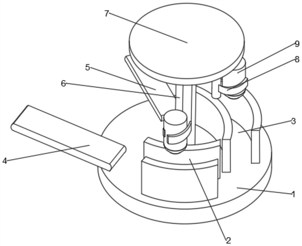
[0028] see Figure 1-7 , in Embodiment 1 of the present invention, an automatic dye barrel cleaning device for textiles, comprising a circular base 1, the upper end of the circular base 1 is sequentially provided with an incoming conveyor belt 4, a cleaning area 2, a drying area 3 and a conveyor belt. Out of the conveyor belt 5, two protective plates 29 are fixedly arranged on the left and right sides of the cleaning area 2 and the drying area 3, and the center of the circular base 1 is provided with a rotating rod 6, and the top end of the rotating rod 6 is fixed An upper top plate 7 is provided, and the lower surface of the upper top plate 7 is evenly fixed with four first telescopic rods 42, and the bottom ends of the first telescopic rods 42 are fixedly provided with a clamping mechanism 8, and the clamping mechanism 8 is clamped and fixed with a dye bucket 9, so that the dye bucket 9 can pass through the cleaning zone 2 and the drying zone 3 in sequence, thereby realizing...

Embodiment 2

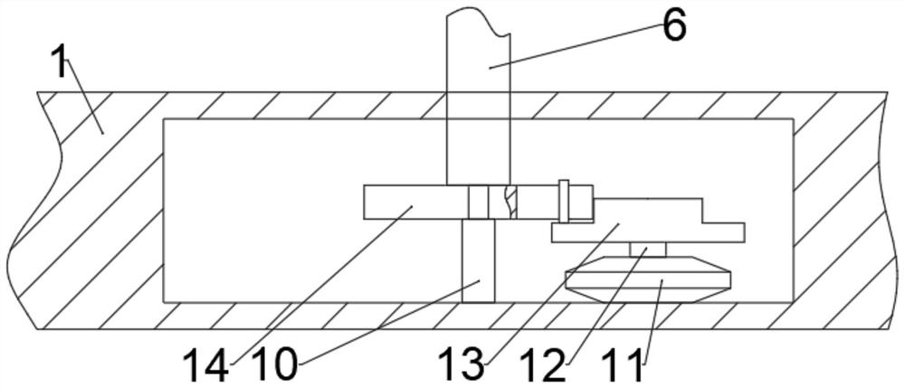
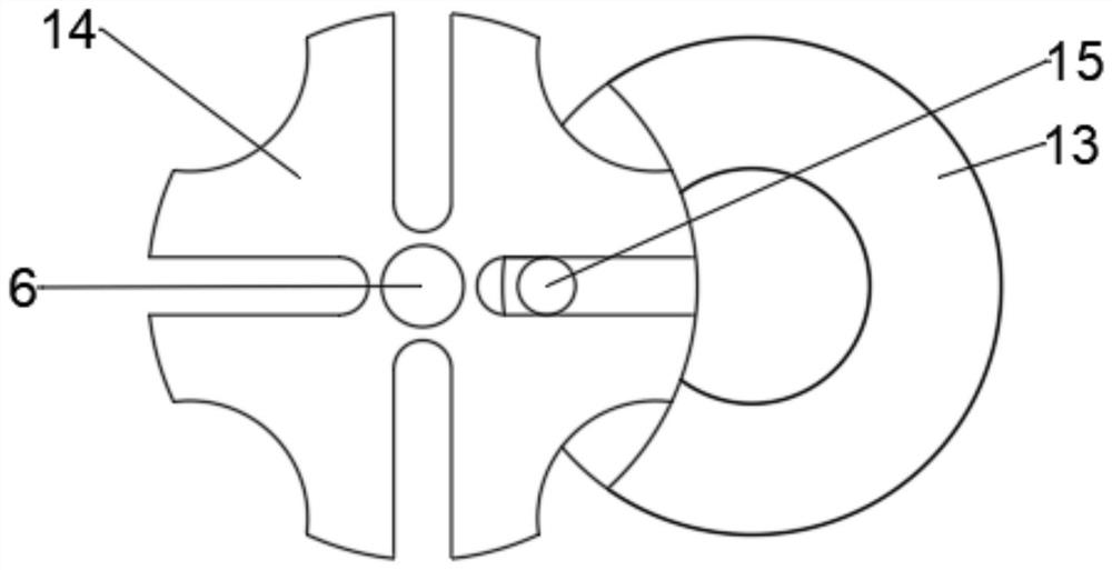
[0030] see Figure 1-7 The main difference between this embodiment 2 and embodiment 1 is that the interior of the circular base 1 below the rotating rod 6 is provided with an intermittent rotating rod 6 mechanism, and the intermittent rotating mechanism includes an intermittent turntable 14, and the intermittent turntable The bottom end of 14 is rotationally connected with the circular base 1 through the connecting rod 10, the lower end of the rotating rod 6 runs through the surface of the circular base 1, and is fixedly connected with the upper surface of the intermittent turntable 14, and the right side of the intermittent turntable 14 is provided with The first motor 11, the bottom end of the first motor 11 is fixedly connected with the circular base 1, the output end of the first motor 11 is fixedly connected with an output shaft 12, and the other end of the output shaft 12 is fixedly connected with a rotating The dial 13, the upper surface of the rotating dial 13 is fixed...


PUM


Abstract

The invention discloses an automatic cleaning device for a textile dye barrel, and relates to the technical field of textile production equipment. The automatic cleaning device comprises a circular base; an incoming conveying belt, a cleaning area, a drying area and an outgoing conveying belt are sequentially arranged at the upper end of the circular base; two protection plates are fixedly arranged on the left side and the right side of the cleaning area and the drying area; a rotating rod is arranged in the center of the circular base; an upper top plate is fixedly arranged at the top end of the rotating rod; four first telescopic rods are evenly fixed to the lower surface of the upper top plate; clamping mechanisms are fixedly arranged at the bottom ends of the first telescopic rods; dye barrels are clamped and fixed to the clamping mechanisms; and an intermittent rotating rod mechanism is arranged in the position, below the rotating rod, of the interior of the circular base. According to the automatic cleaning device for the textile dye barrel provided by the invention, by arranging the incoming conveying belt, the cleaning area, the drying area and the outgoing conveying belt, full-automatic cleaning of the textile dye barrel is achieved, the cleaning efficiency of the dye barrel is effectively improved, and a large number of manpower resources are saved.

Description

technical field [0001] The invention relates to the technical field of textile production equipment, in particular to an automatic cleaning device for textile dye barrels. Background technique [0002] During the dyeing process in the dyeing machine, the fabric needs to be immersed in the dye solution, and the dye solution needs to be used as the power of the dyeing cycle. Dye liquor is composed of chemical raw materials, pigments, auxiliaries, etc. (dye chemicals) dissolved in the dye bucket outside the dyeing machine cylinder, stirred evenly, and then pumped into the main cylinder of the dyeing machine and mixed with water in the main cylinder. [0003] The existing textile dye buckets are all cleaned manually or semi-automatically, which not only consumes a lot of labor and financial resources, but also has low cleaning efficiency for the textile dye buckets. Contents of the invention [0004] The object of the present invention is to provide an automatic cleaning devi...

Claims


Application Information

Patent Timeline
Patent Type & Authority Applications(China)
IPC IPC(8): B08B9/34B08B9/30B08B9/42B08B13/00F26B21/00
CPCB08B9/34B08B9/30B08B9/42B08B9/0813B08B13/00F26B21/00
Inventor 顾忠
Owner 苏州开江纺织品有限公司
Why Eureka
Try Eureka