Supercharge Your Innovation With Domain-Expert AI Agents!

Aerospace material pressure forming device

An aerospace, pressure forming technology, used in springs/shock absorbers, vibration suppression adjustment, mechanical equipment, etc., to achieve the effect of convenient and quick connection

Inactive Publication Date: 2021-05-28
尚海军
View PDF1 Cites 0 Cited by
  • Summary
  • Abstract
  • Description
  • Claims
  • Application Information

AI Technical Summary

Problems solved by technology

The shortcoming of this invention is that the quick connection groove cannot be formed directly by pressure

Method used


Image

  • Aerospace material pressure forming device
  • Aerospace material pressure forming device
  • Aerospace material pressure forming device

Examples


specific Embodiment approach 1

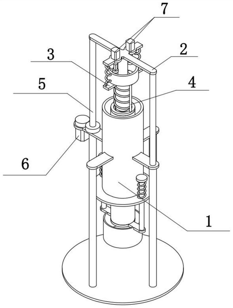
[0031] Combine below Figure 1-8 To illustrate this embodiment, the aerospace material pressure molding device includes a variable housing assembly 1, a pressing assembly 2, a processing assembly 3, an adjusting assembly 4, a lifting assembly 5, a driving assembly 6, and a rotating assembly 7. The pressing assembly Component 2 is slidingly connected to the variable housing component 1, the processing component 3 is connected to the pressing component 2, the adjusting component 4 is connected to the processing component 3, the lifting component 5 is fixedly connected to the pressing component 2, and the lifting component 5 is rotatably connected to the On the variable housing assembly 1, the driving assembly 6 is fixedly connected to the variable housing assembly 1, the driving assembly 6 and the lifting assembly 5 are engaged for transmission, and there are two rotating assemblies 7, both of which are fixedly connected to the pressing On the component 2, the two rotating compo...

specific Embodiment approach 2

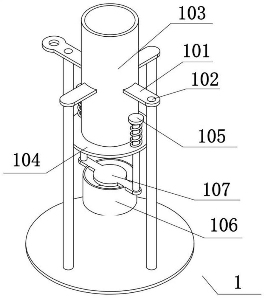
[0034] Combine below Figure 1-8 To illustrate this embodiment, the variable housing assembly 1 includes a base 101, a guide hole 102, a forming tube 103, a guide plate 104, a guide rod 105, a loading frame 106, and a sealing plate 107, and the base 101 is provided with two Guide hole 102, forming tube 103 is fixedly connected on the base 101, the lower end of forming tube 103 is fixedly connected with guide plate 104, and guide plate 104 is slidably connected with two guide rods 105, between two guide rods 105 and guide plate 104 Springs are fixedly connected between them, a loading frame 106 is fixedly connected to the two guide rods 105 , and a sealing plate 107 is fixedly connected to the loading frame 106 .

specific Embodiment approach 3

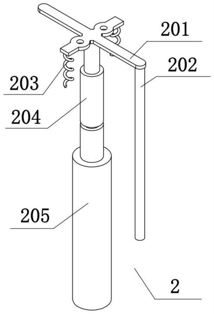
[0036] Combine below Figure 1-8To illustrate this embodiment, the press-down assembly 2 includes a press-down bracket 201, a press-down guide rod 202, a buffer spring 203, a threaded rod 204, and a push-out rod 205, and the press-down bracket 201 is fixedly connected with a press-down guide rod 202, The push-down guide rod 202 is slidingly connected in one of the guide holes 102, two buffer springs 203 are fixedly connected to the push-down bracket 201, the threaded rod 204 is fixedly connected to the push-down bracket 201, and the push-out rod 205 is fixedly connected to the threaded rod 204 superior.


PUM


Abstract

The invention relates to the technical field of pressure forming equipment, in particular to an aerospace material pressure forming device which has the advantage that a quick connecting groove can be directly formed through pressurization and comprises a variable shell assembly, a pressing assembly, a machining assembly, an adjusting assembly, a lifting assembly, a driving assembly and rotating assemblies. The pressing assembly is slidably connected to the variable shell assembly, the machining assembly is connected to the pressing assembly, the adjusting assembly is connected to the machining assembly, the lifting assembly is fixedly connected to the pressing assembly, the lifting assembly is rotationally connected to the variable shell assembly, and the driving assembly is fixedly connected to the variable shell assembly. The driving assembly is in meshing transmission with the lifting assembly, the two rotating assemblies are both fixedly connected to the pressing assembly, and the two rotating assemblies are in friction transmission with the adjusting assembly.

Description

technical field [0001] The invention relates to the technical field of pressure molding equipment, in particular to a pressure molding device for aerospace materials. Background technique [0002] The invention with the publication number CN210026442U discloses a pressurized molding device for alloy materials, which includes a housing, first slide grooves are opened on both sides of the inner cavity of the housing, and first slide grooves are arranged on both sides of the bottom of the inner cavity of the housing. The buffer device, the inner cavity of the housing is provided with a lower mold base. The utility model is provided with a housing, a first chute, a buffer device, a lower mold base, a shock absorbing spring, a telescopic rod, a buffer spring, an oil pressure cylinder, a horizontal plate, a pressing plate, a bottom plate, a sliding plate, a second chute and a second The mutual cooperation of the sliders achieves the advantages of good shock absorption and bufferi...

Claims


Application Information

Patent Timeline
Patent Type & Authority Applications(China)
IPC IPC(8): B21D17/02F16F15/067
CPCB21D17/02F16F15/067
Inventor 尚海军
Owner 尚海军
Features
  • R&D
  • Intellectual Property
  • Life Sciences
  • Materials
  • Tech Scout
  • Unparalleled Data Quality
  • Higher Quality Content
  • 60% Fewer Hallucinations
Learn More