
Hydraulic lifting workbench for laser cutting machine

A technology of laser cutting machine and hydraulic lifting, which is applied in laser welding equipment, manufacturing tools, metal processing equipment, etc., and can solve problems such as height difference, uneven workbench, and processing errors

Pending Publication Date: 2021-05-28
杭州圣通智能科技有限公司
View PDF0 Cites 0 Cited by
  • Summary
  • Abstract
  • Description
  • Claims
  • Application Information

AI Technical Summary

Problems solved by technology

[0004] The purpose of the present invention is to solve the problem that the traditional interactive processing table has a certain height difference. When cutting the same size, the laser head needs to be adjusted, which will cause processing errors, and the existing hydraulic lifting The table is equipped with hydraulic cylinders vertically through the four corners, so that when a hydraulic cylinder deviates, it will cause the overall workbench to be out of level, reduce processing accuracy and other problems, and provide a hydraulic lifting workbench for laser cutting machines

Method used


Image

  • Hydraulic lifting workbench for laser cutting machine
  • Hydraulic lifting workbench for laser cutting machine
  • Hydraulic lifting workbench for laser cutting machine

Examples


Embodiment Construction

[0022] The following will clearly and completely describe the technical solutions in the embodiments of the present invention with reference to the accompanying drawings in the embodiments of the present invention. Obviously, the described embodiments are only some, not all, embodiments of the present invention. Based on the embodiments of the present invention, all other embodiments obtained by persons of ordinary skill in the art without making creative efforts belong to the protection scope of the present invention.

[0023] In describing the present invention, it should be understood that the terms "longitudinal", "transverse", "length", "width", "thickness", "upper", "lower", "front", "rear", " The orientation or positional relationship indicated by "left", "right", "vertical", "horizontal", "top", "bottom", "inner", "outer", etc. is based on the orientation or positional relationship shown in the drawings, It is only for the convenience of describing the present inventio...


PUM


Abstract

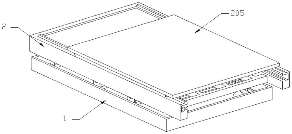
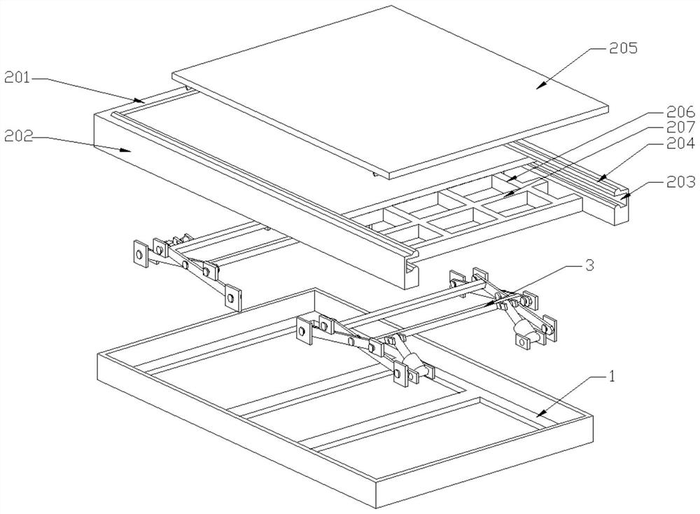
The invention discloses a hydraulic lifting workbench for a laser cutting machine. The hydraulic lifting workbench comprises a chassis, a lifting table is arranged above the chassis, hydraulic lifting devices are symmetrically arranged at the two ends of the position between the chassis and the lifting table, and the hydraulic lifting devices are connected with the chassis and the lifting table in a welded manner; the lifting table comprises a connecting beam, guide rails are arranged at the two ends of the connecting beam, guide grooves are formed in the inner side faces of the guide rails, barrier strips are arranged on the upper surfaces of the guide rails and the lower surfaces of the guide grooves, movable workbenches are arranged on the upper surfaces of the guide rails and in the guide grooves, and a plurality of longitudinal beams are transversely and evenly arranged between the guide rails at the two ends; and a plurality of cross beams are longitudinally and evenly arranged between the guide rails at the two ends, and the longitudinal beams and the cross beams are connected with the guide rails in a welded manner. By means of the hydraulic lifting workbench, the supporting levelness and the machining height of the workbench can be guaranteed, the machining precision is improved, and the air draft and dust removal effects can be improved.

Description

technical field [0001] The invention belongs to the technical field of laser cutting machine processing and manufacturing, and in particular relates to a hydraulic lifting worktable for a laser cutting machine. Background technique [0002] Laser cutting is to focus the laser emitted from the laser into a high power density laser beam through the optical path system. The laser beam irradiates the surface of the workpiece to make the workpiece reach the melting point or boiling point, and at the same time, the high-pressure gas coaxial with the beam blows away the molten or vaporized metal. With the movement of the relative position of the beam and the workpiece, the material will eventually form a slit, so as to achieve the purpose of cutting. [0003] Existing laser cutting machines mostly use interactive processing tables, which can improve work efficiency, but the traditional interactive processing tables have a certain height difference, and the laser head needs to be a...

Claims


Application Information

Patent Timeline
IPC IPC(8): B23K26/38B23K26/70
CPCB23K26/38B23K26/702
Inventor 车艾建车畅陈大盟赵帅姚杰丁朋
Owner 杭州圣通智能科技有限公司
Learn More