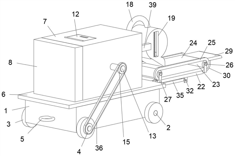
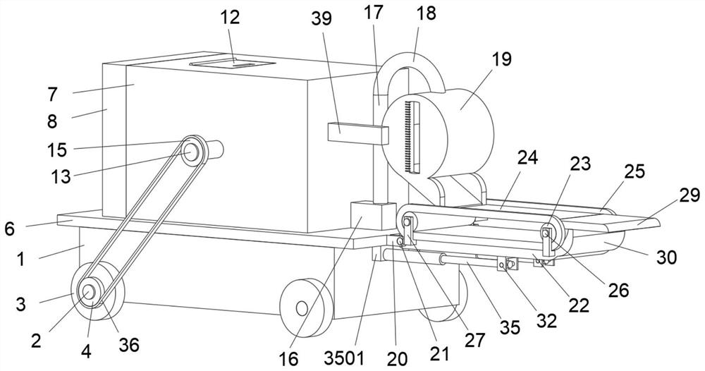
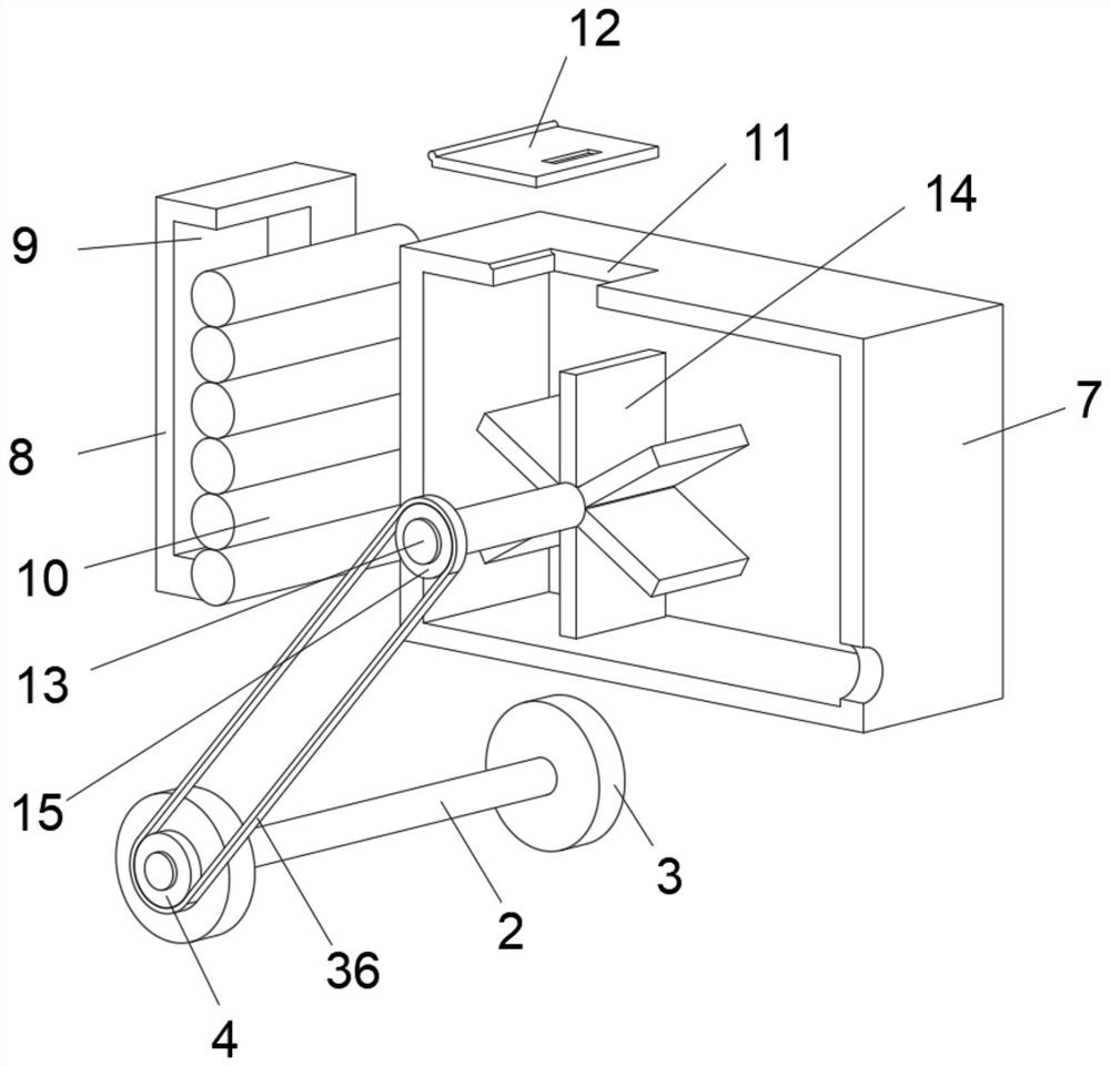
Highway maintenance vehicle asphalt metering and conveying device

A technology for conveying devices and maintenance vehicles, which is applied to cleaning devices, conveyor objects, transportation and packaging, etc. It can solve problems such as time-consuming, no mixing structure, and asphalt splashing, so as to prevent excessive repair time and guarantee Patency, efficiency-enhancing effects

Active Publication Date: 2021-02-23
CHECC DATA CO LTD +1
View PDF10 Cites 0 Cited by
  • Summary
  • Abstract
  • Description
  • Claims
  • Application Information

AI Technical Summary

Problems solved by technology

[0002] Highway maintenance vehicle is a special vehicle specially developed for road maintenance and repair operations. It is convenient for carrying staff, reloading tools, loading and unloading construction materials, and is widely used in municipal and various fields Maintenance and repair of grade roads. In the daily use of asphalt roads, the ground will be damaged due to the passing of vehicles. After a long period of accumulation, cracks and missing blocks will occur, resulting in uneven roads. At this time, it is necessary to asphalt the roads. Filling and repairing, the existing method is to use the road maintenance vehicle to carry the asphalt conveying device to transport the asphalt to repair the road surface
[0003] After searching, the patent with the publication number CN207121784U discloses a kind of asphalt metering and conveying device for road maintenance vehicles. The inventor discovered the prior art in the process of realizing the utility model There are the following problems: 1. There is no mixing structure in the asphalt tank of the existing device. When the road maintenance vehicle transports the device to the damaged part of the road surface, the asphalt in the tank will cool and solidify due to standing for a long time. In this way, the asphalt cannot be extracted from the asphalt tank. At this time, if you want to heat the asphalt in the asphalt tank and then extract it, it will consume a lot of time, which is not conducive to improving the efficiency of road repair and maintenance, and will greatly affect the road. 2. The height of the discharge pipe in the existing device from the ground is too high. When the staff uses this device to output the asphalt, it is easy to cause splashing, which is easy to cause pollution and also cause the splashed asphalt to form a convex around the damaged part. It will cause the problem of uneven road surface, which will bring unnecessary troubles to the work of the staff. In view of this, we propose an asphalt metering and conveying device for road maintenance vehicles
[0004] After searching, the publication number is CN210456182U discloses a kind of bitumen conveying device, the inventor finds the following problems in the prior art in the process of realizing the utility model: 3. The existing device cannot measure and transport asphalt, which is not conducive to the control and budget of the asphalt amount when the staff performs road maintenance work, which will cause waste; 4. There is no blocking structure on both sides of the second belt in the device, when the asphalt When it falls on the second belt and is transported, it is very easy to cause the asphalt to fall off the belt from both sides, so that the staff cannot accurately control the conveying direction of the asphalt, which is not conducive to the development of road maintenance work. In view of this, we propose Asphalt metering and conveying device for road maintenance vehicle

Method used


Image

  • Highway maintenance vehicle asphalt metering and conveying device
  • Highway maintenance vehicle asphalt metering and conveying device
  • Highway maintenance vehicle asphalt metering and conveying device

Examples


Embodiment Construction

[0030] In describing the present invention, it should be understood that the terms "center", "longitudinal", "transverse", "length", "width", "thickness", "upper", "lower", "front", " Orientation indicated by rear, left, right, vertical, horizontal, top, bottom, inside, outside, clockwise, counterclockwise, etc. The positional relationship is based on the orientation or positional relationship shown in the drawings, and is only for the convenience of describing the present invention and simplifying the description, rather than indicating or implying that the referred device or element must have a specific orientation, be constructed and operated in a specific orientation, Therefore, it should not be construed as limiting the invention.

[0031] In the description of the present invention, "plurality" means two or more, unless otherwise specifically defined.

[0032] In the description of the present invention, it should be noted that, unless otherwise specified and limited, t...


PUM


Abstract

The invention discloses a highway maintenance vehicle asphalt metering and conveying device, and belongs to the technical field of asphalt conveying devices. The highway maintenance vehicle asphalt metering and conveying device comprises a base, two wheel shafts are symmetrically arranged on the lower portion of the base in a penetrating mode, the right end of the wheel shaft located on the frontside is sleeved with a driving wheel, and a fixing plate is fixedly arranged on the top face of the wheel shaft. An asphalt box is fixedly arranged in the middle of the top face of the fixing plate, and a rotating column penetrates through the middle of the right wall of the asphalt box. The left end of the rotating column penetrates through the right wall of the asphalt box and extends into the asphalt box, a plurality of stirring blades are annularly and fixedly arranged on the outer wall of the left side of the rotating column at equal intervals, the right portion of the rotating column issleeved with a driven wheel, and a conveying belt is connected between the driven wheel and the driving wheel; an asphalt pump is fixedly arranged on the rear side of the top face of the fixing plate,the output end of the asphalt pump is connected with a vertical pipe, and the upper end of the vertical pipe is connected with a metal hose, a metering assembly is arranged on the rear side of the asphalt box. According to the device, asphalt cannot be solidified due to standing for a long time in the conveying process, workers can be assisted in accurately controlling the conveying amount of theasphalt, and convenience and rapidness are achieved.

Description

technical field [0001] The invention relates to the technical field of asphalt conveying devices, in particular to an asphalt metering and conveying device for a road maintenance vehicle. Background technique [0002] Road maintenance vehicle is a special vehicle specially developed for the needs of road maintenance and repair operations. It is convenient for carrying staff, reloading tools, and loading and unloading construction materials. It is widely used in the maintenance and repair of municipal and roads at all levels. In the daily use of asphalt roads, ground Damage will occur due to the passing of vehicles, and after long-term accumulation, cracks and missing blocks will occur, resulting in uneven roads. At this time, it is necessary to fill and repair the road with asphalt. The existing methods are carried by road maintenance vehicles. The asphalt conveying device then transports asphalt to repair the road surface. [0003] After searching, the patent with the publ...

Claims


Application Information

Patent Timeline
Patent Type & Authority Applications(China)
IPC IPC(8): E01C23/03E01C23/09B65G45/12
CPCE01C23/03E01C23/0973B65G45/12
Inventor 杨义武
Owner CHECC DATA CO LTD
Why Eureka
Try Eureka