Shoe sole polishing equipment

A technology for shoe soles and equipment, which is applied in the direction of grinding/polishing equipment, metal processing equipment, grinding machines, etc., can solve the problems of unstable composite bonding structure of shoe soles, lower product quality, high strength and high grinding angle, and improve grinding quality and Grinding efficiency, improving sampling accuracy, and improving the effect of grinding precision

Pending Publication Date: 2021-05-28
东莞云展智能装备有限公司
View PDF0 Cites 2 Cited by
  • Summary
  • Abstract
  • Description
  • Claims
  • Application Information

AI Technical Summary

Problems solved by technology

[0003] The traditional grinding of shoe soles is done by manually operating a grinding machine with a grinding disc or a grinding head. However, the traditional grinding of shoe soles is controlled by manual operation, and the quality of the grinding depends entirely on the skills and experience of the operators.
Especially when the surface of the sole is fully polished, the surface and sides of the sole need to be polished and thickened separately, and two different grinding machines equipped with a grinding disc and a grinding head are required to perform two-stage grinding on the sole, which is very time-consuming. strenuous
Among them, grinding the surface of the sole by manually operating the disc grinder may easily cause partial repeated grinding and uneven surface grinding, resulting in unstable composite bonding structure of the sole and reducing product quality; When grinding the side of the sole, due to the unevenness of the edge of the sole, the control of the strength and grinding angle is higher, and the grinding process is extremely difficult

Method used


Image

  • Shoe sole polishing equipment
  • Shoe sole polishing equipment
  • Shoe sole polishing equipment

Examples


Embodiment Construction

[0026] The following are only preferred embodiments of the present invention, and therefore do not limit the protection scope of the present invention.

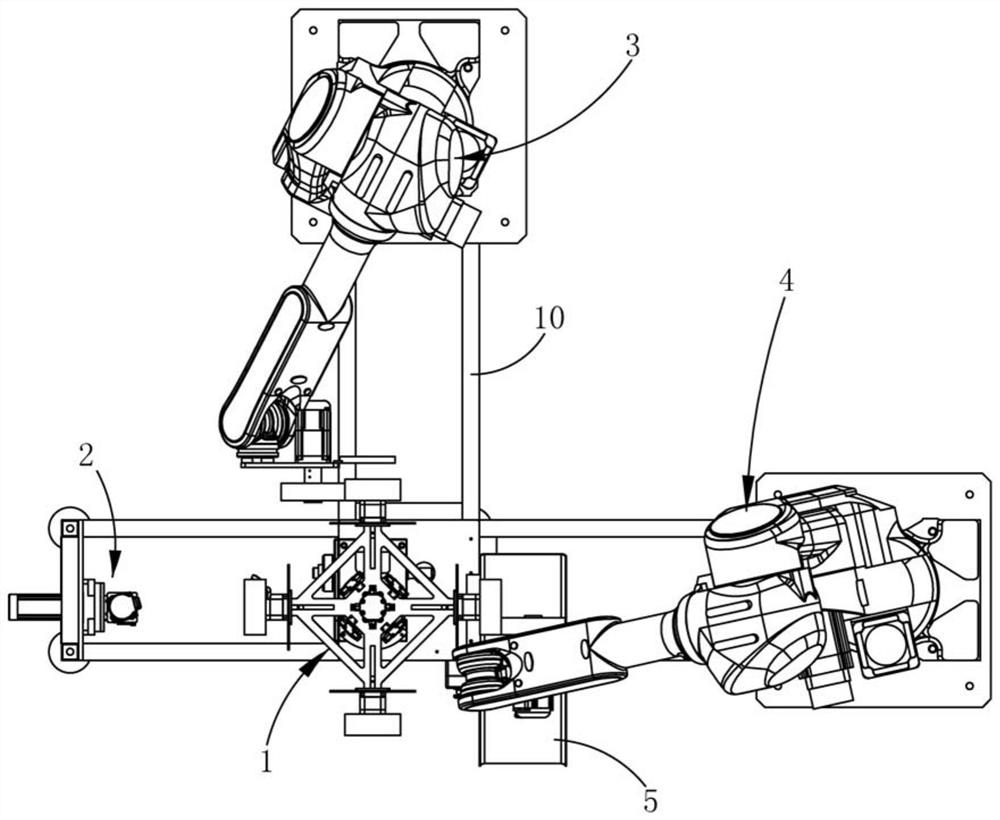
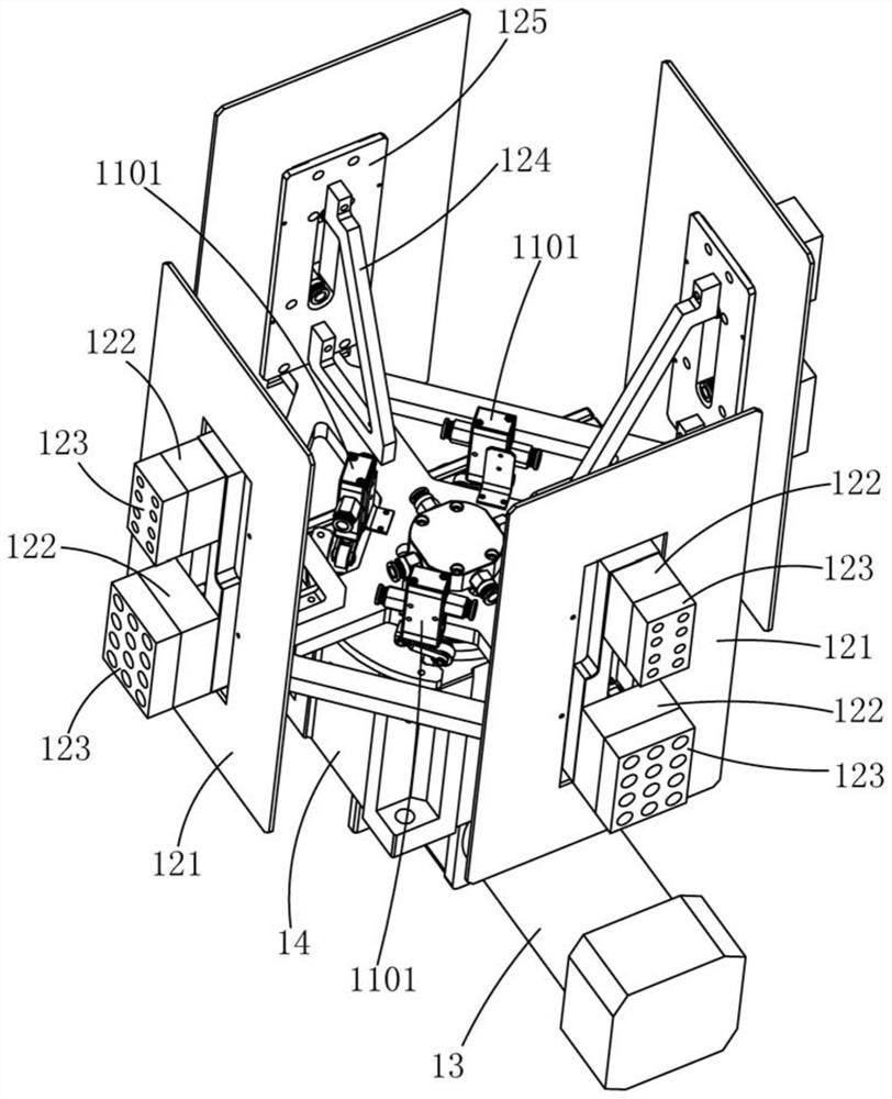
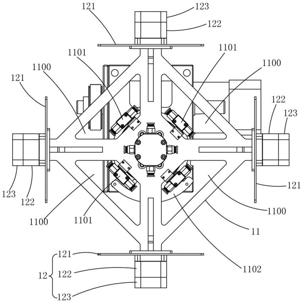
[0027] A kind of shoe sole grinding equipment, such as Figure 1 to Figure 4 As shown, it includes a control device, a frame 10, and a sole gripping device 1 arranged at the center of the frame 10. The first side of the sole gripping device 1 is provided with a feeding position, and the second side is provided with a sampling device for collecting soles. position, the third side is provided with the grinding position 1 used for grinding the side of the sole and the 4th side is provided with the grinding position 2 used as the surface of the sole for grinding; the side of the shoe sole gripping device 1 near the sampling position is provided with a A shoe sole scanning device 2 for clamping position data and three-dimensional contour model data, a side grinding device 3 is arranged on a side near the grinding position one, a f...


PUM


Abstract

The invention discloses shoe sole polishing equipment. The shoe sole polishing equipment comprises a control device, a machine frame and a shoe sole grabbing device which is arranged in the center of the machine frame, a feeding position is arranged on the first side of the shoe sole grabbing device, a sampling position used for collecting shoe soles is arranged on the second side of the shoe sole grabbing device, a first polishing position used for polishing the side faces of the shoe soles is arranged on the third side of the shoe sole grabbing device, a second polishing position used for polishing the surfaces of the shoe soles is arranged on the fourth side of the shoe sole grabbing device, a shoe sole scanning device used for collecting shoe sole clamping position data and three-dimensional contour model data is arranged on one side, close to the sampling position, of the shoe sole grabbing device, a side face polishing device is arranged on one side, close to the first polishing position, of the shoe sole grabbing device, a front face polishing device is arranged on one side, close to the second polishing position, of the shoe sole grabbing device, and the shoe sole scanning device, the side face polishing device and the front face polishing device are electrically connected with a control device. Compared with the prior art, manual shoe sole polishing of a composite polishing procedure is omitted, and the polishing quality and the polishing efficiency are improved.

Description

technical field [0001] The invention relates to the technical field of shoemaking equipment, in particular to a shoe sole grinding equipment. Background technique [0002] The material used to make the sole should be light, highly elastic, and wear-resistant, so as to reduce the energy consumption of the user, and improve the wearing comfort and service life to a certain extent. In the existing shoemaking process, secondary molding is often used for property The soft middle layer of the sole and the outer layer of the wear-resistant sole are pressed and molded to form a finished shoe sole with good comfort and high wear resistance. In order to improve the quality of the secondary molding and avoid wrinkling on the outer surface of the finished shoe sole, it is necessary to Secondary molding sands the sole material. [0003] The traditional grinding of soles is to manually operate a grinding machine with a grinding disc or a grinding head to grind the soles. However, the tra...

Claims


Application Information

Patent Timeline
Patent Type & Authority Applications(China)
IPC IPC(8): B24B19/22B24B27/00B24B41/00B24B41/06B24B49/12B24B51/00A43D8/34A43D8/36
CPCA43D8/34A43D8/36B24B19/22B24B27/0023B24B27/0069B24B27/0076B24B27/0084B24B41/005B24B41/068B24B49/12B24B51/00
Inventor 王文平
Owner 东莞云展智能装备有限公司
Why Eureka
Try Eureka