Pipeline corrosion prevention and rust removal device
A pipe and installation groove technology, which is applied in the direction of grinding drive device, grinding/polishing safety device, grinding machine, etc., can solve the problems of easy adhesion on the surface of the pipe, hinder the grinding of the grinding disc, and affect the grinding efficiency, so as to avoid grinding , Avoid damage, improve the effect of grinding efficiency
- Summary
- Abstract
- Description
- Claims
- Application Information
AI Technical Summary
Problems solved by technology
Method used
Image

Examples
Embodiment Construction
[0023] The following will clearly and completely describe the technical solutions in the embodiments of the present invention with reference to the accompanying drawings in the embodiments of the present invention. Obviously, the described embodiments are only some, not all, embodiments of the present invention.
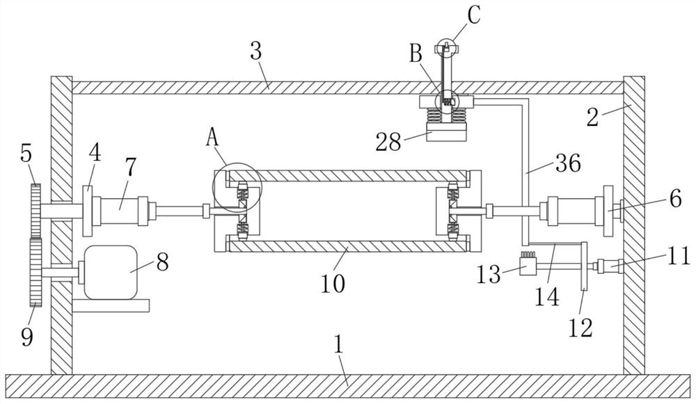
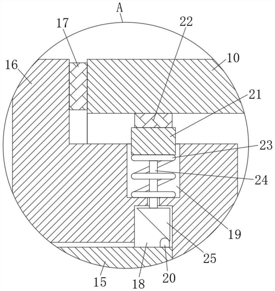
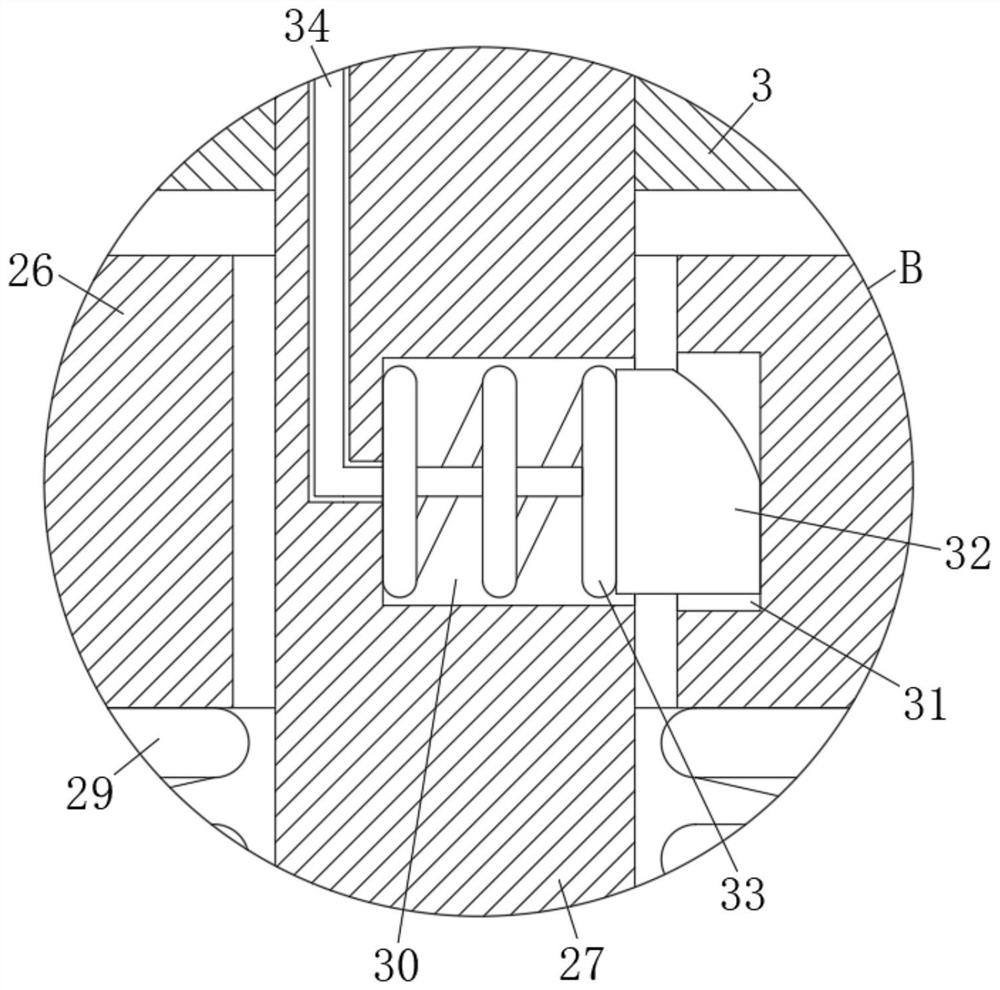
[0024] refer to Figure 1-4 , a pipe anticorrosion and derusting device, comprising a base 1, two support rods 2 are fixedly installed on the top of the base 1, a connecting rod 3 is fixedly connected between the two support rods 2, and one of the support rods 2 is rotatably connected with a rotating Rod 4, the other supporting rod 2 is connected with a rotating plate 6 for rotation, the first electric push rod 7 is fixedly installed on the rotating rod 4 and the rotating plate 6, and the telescoping ends of the two first electric push rods 7 are provided with resist Tightening mechanism, the pipeline 10 to be polished is slidably connected between the two abutting m...
PUM
 Abstract
Description
Claims
Application Information