Full-automatic unattended propellant sampling machine and preparation method

A propellant, fully automatic technology, applied in the direction of comprehensive factory control, metal processing, etc., can solve the problems of low preparation efficiency, unautomated processing technology, safety risks, etc., to achieve improved safety, low cost, and convenient manufacturing Effect

Active Publication Date: 2021-05-28
HUBEI SANJIANG AEROSPACE JIANGHE CHEM TECH
View PDF5 Cites 0 Cited by
  • Summary
  • Abstract
  • Description
  • Claims
  • Application Information

AI Technical Summary

Problems solved by technology

[0003] The existing sample preparation process uses semi-automatic equipment. In the preparation process, manual assistance is required to complete multiple different processes, which cannot realize a fully automated processing technology. At present, the basic workflow of sample preparation is as follows: Figure 15
[0004] It ca

Method used


Image

  • Full-automatic unattended propellant sampling machine and preparation method
  • Full-automatic unattended propellant sampling machine and preparation method
  • Full-automatic unattended propellant sampling machine and preparation method

Examples


Example Embodiment

[0054] Example 1:

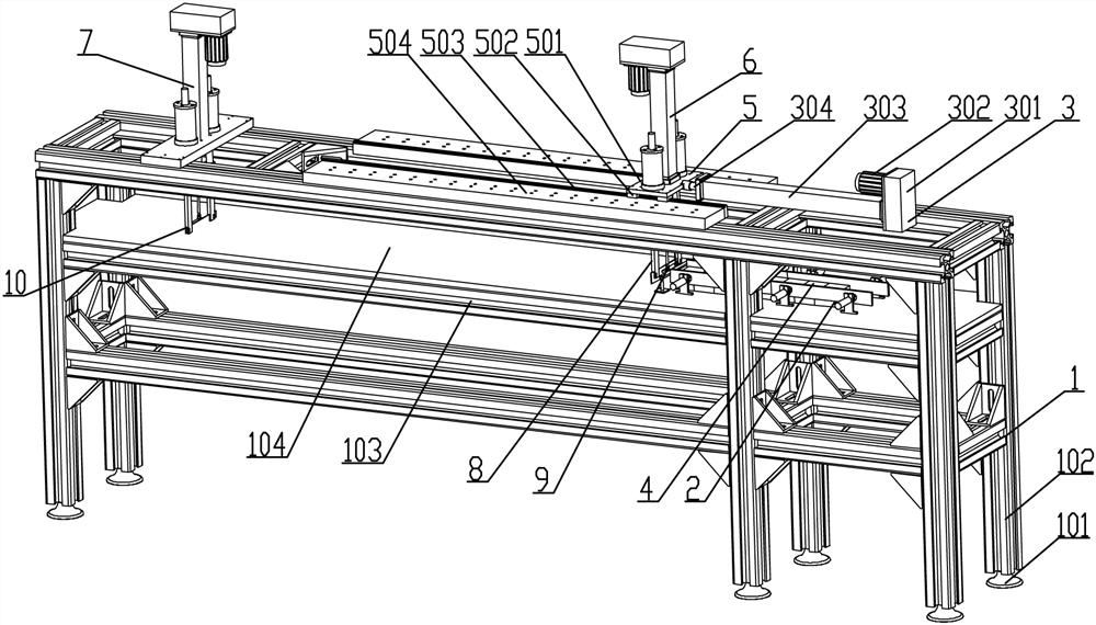
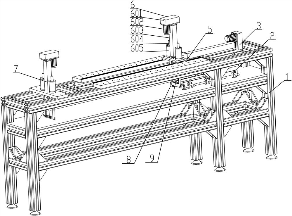
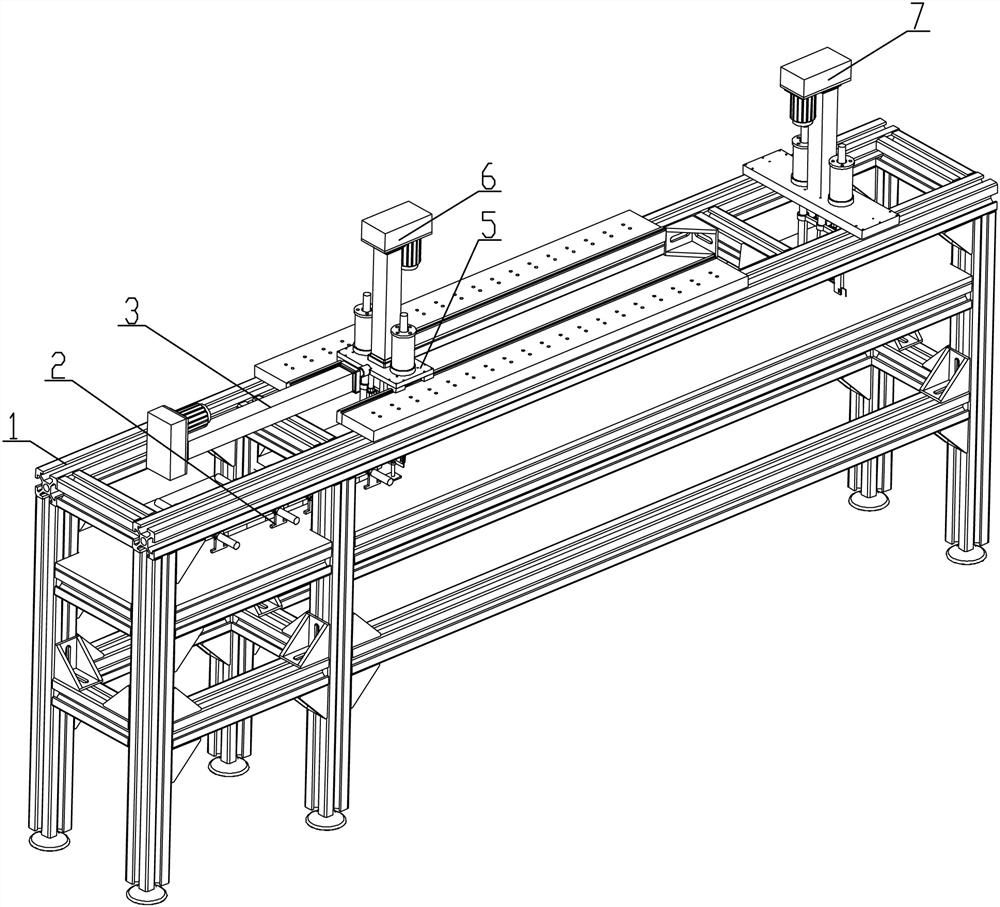
[0055] see Figure 1-13 , a fully automatic unattended propellant prototype preparation machine, which includes a frame structure 1, and a sliding rail mechanism 5 is arranged in the top middle part of the frame structure 1. The first cutting power mechanism 6, the bottom end of the first cutting power mechanism 6 is fixed with a first cutter assembly 8; the sliding rail mechanism 5 is connected with the propulsion mechanism 3 for pushing it to move, and the propulsion mechanism 3 is fixed on the machine. The top of the frame structure 1; the feed guide structure 2 for conveying the propellant blanks 4 is connected directly below the first cutting knife assembly 8; The medicine rod is cut into a dumbbell-shaped second cutting power mechanism 7, and the bottom end of the second cutting power mechanism 7 is fixed with a second cutter assembly 10. By adopting the prototype machine with the above structure, the overall design realizes unattended parameterized...

Example Embodiment

[0073] Example 2:

[0074] see Figure 14 , a method for preparing propellant samples by an automatic unattended propellant sample preparation machine, comprising the following steps:

[0075] Step 1: Place the preliminarily cut propellant blanks 4 between the segmented baffles 203 on both sides of the feed guide structure 2, and push the propellant blanks 4 placed in a straight line along the feed guide structure 2 It is conveyed forward to make it reach the position just below the first cutter assembly 8;

[0076]Step 2: After the propellant blank 4 is in place, start the first cutting power mechanism 6, drive the second push rod 606 through the second explosion-proof servo motor 602 and the second transmission box 601, and drive the first push rod 606 through the second push rod 606. The knife assembly 8 slices the propellant blank 4 through the first cutting knife 803 of the first cutting knife assembly 8. During the slicing process, the up and down stroke height of the ...


PUM


Abstract

The invention provides a full-automatic unattended propellant sampling machine and a preparation method. The middle of the top of a rack structure is provided with a sliding rail mechanism, the sliding rail mechanism is fixedly provided with a first cutting-off power mechanism used for slicing propellants, and the bottom end of the first cutting-off power mechanism is fixedly provided with a first cutter assembly; the sliding rail mechanism is connected with a pushing mechanism used for pushing the sliding rail mechanism to move, and the pushing mechanism is fixed to the top of the rack structure; a feeding guide structure used for conveying propellant powder blanks is in butt joint under the first cutter assembly; a second cutting-off power mechanism used for cutting cut medicine strips into dumbbell shapes is mounted on the tail section of the rack structure in a supporting mode; and a second cutter assembly is fixed to the bottom end of the second cutting-off power mechanism. According to the sampling machine, full-automatic equipment is adopted for completing the whole sampling technological process, and parameterized cutting, slicing and slitting of the propellant powder blanks and machining of dumbbell-shaped test pieces are achieved in an unattended mode.

Description

technical field [0001] The invention relates to the technical field of solid propellant sample preparation, in particular to a fully automatic unattended propellant sample preparation machine and a preparation method. Background technique [0002] In the process of testing the performance of solid rocket motor propellants, it is necessary to parameterize the propellant billets for cutting, slicing, slicing and finally cutting them into dumbbell shapes, so as to facilitate the subsequent testing process. [0003] The existing sample preparation process uses semi-automatic equipment. In the preparation process, manual assistance is required to complete multiple different processes, which cannot realize a fully automated processing technology. At present, the basic workflow of sample preparation is as follows: Figure 15 . [0004] It can be seen from the above-mentioned process flow that there are many different processes in the preparation process that need to be manually inv...

Claims


Application Information

Patent Timeline
IPC IPC(8): B26D1/10B26D7/06B26D7/26B26D7/18
CPCB26D7/0608B26D7/2628B26D1/10B26D7/18Y02P90/02
Inventor 徐红菊王娜黄水生闫志佳蔡银丽申琳李卫
Owner HUBEI SANJIANG AEROSPACE JIANGHE CHEM TECH
Why Eureka
Try Eureka