
Burr removing equipment suitable for outer surface of ball bladder, and removing method

A technology for removing burrs and bladders, which is applied in metal processing, etc., and can solve problems such as the influence of burrs removal rate, uneven processing quality, time-consuming and labor-intensive problems, and achieve the effects of high cutting consistency rate, fast cutting speed and simple operation

Inactive Publication Date: 2021-05-28
无锡市爱可赛体育用品有限公司
View PDF8 Cites 0 Cited by
  • Summary
  • Abstract
  • Description
  • Claims
  • Application Information

AI Technical Summary

Problems solved by technology

[0003] In the production of bladders, it is necessary to perform burrs on the outer surface of the bladders. However, most of the existing burrs treatment processes manually turn over the bladders one by one, and cut the burrs during the overturning process. This process is not only time-consuming and laborious. Moreover, the removal rate of burrs is often affected by the subjective factors of the operator, and then there is a problem of uneven processing quality after burrs are processed.

Method used


Image

  • Burr removing equipment suitable for outer surface of ball bladder, and removing method
  • Burr removing equipment suitable for outer surface of ball bladder, and removing method
  • Burr removing equipment suitable for outer surface of ball bladder, and removing method

Examples


Embodiment 1

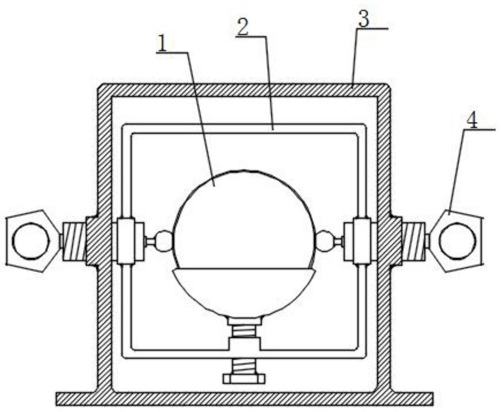
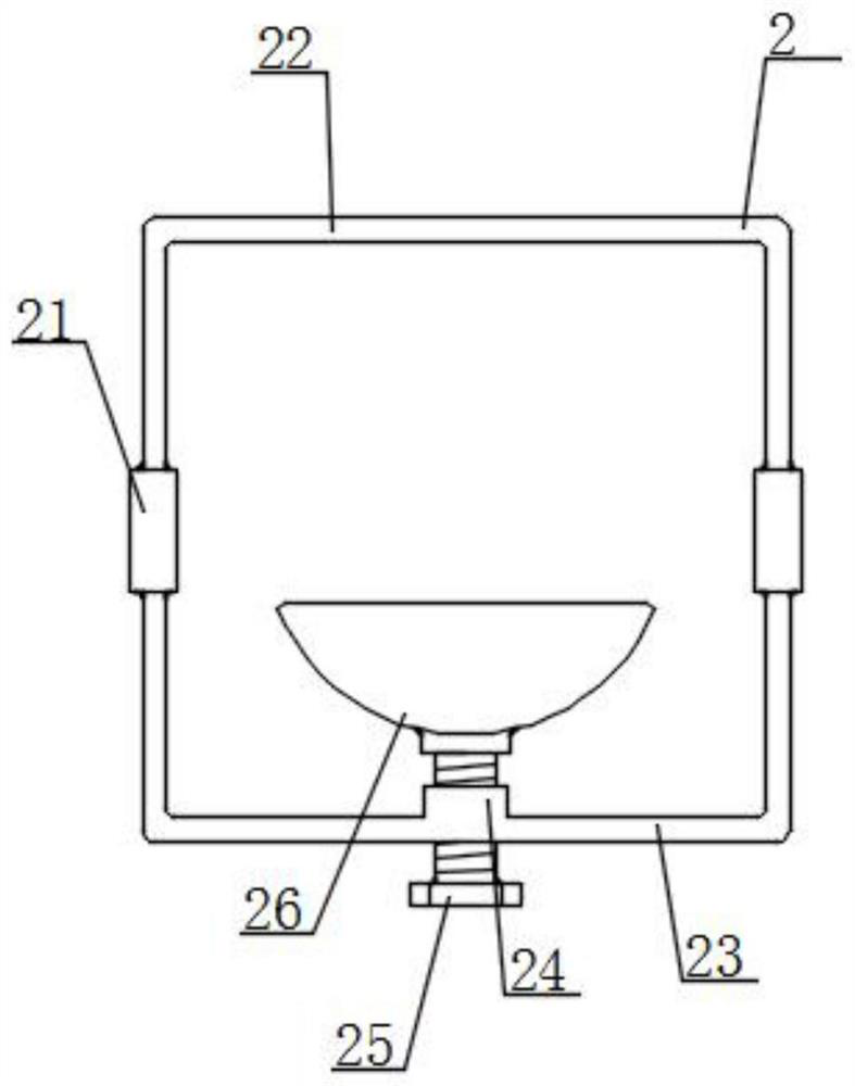
[0027] Such as Figure 1-2 As shown, a device suitable for deburring the outer surface of a ball bladder includes a bearing frame 3 and an internal thread channel. An overturning component 2 is provided, and both sides of the overturning component 2 are penetrated by the drive component 4;

[0028] Turnover assembly 2 comprises collar 21, U-shaped rod 22, U-shaped positioning rod 23, sleeve pipe 24, threaded insert rod 25 and cutting bowl 26, and U-shaped rod 22 is arranged in the carrying frame 3, and the opposite part of U-shaped rod 22 A U-shaped positioning rod 23 is provided; a collar 21 is provided at the protruding part of the driving assembly 4 relative to the bearing frame 3, and the collar 21 is set on the driving assembly 4; the ends of the U-shaped rod 22 and the U-shaped positioning rod 23 are symmetrical Fixed to both sides of the collar 21, a sleeve 24 runs through the midpoint of the U-shaped positioning rod 23, and a threaded insertion rod 25 is bolted inside...

Embodiment 2

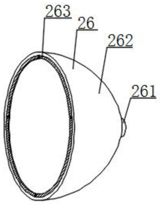
[0032] Such as Figure 1-3 As shown, a device suitable for deburring the outer surface of the bladder, the cutting bowl 26 is covered with a bladder 1, and the two ends of the bladder 1 are clamped by the drive assembly 4; the cutting bowl 26 includes a sleeve cup 261, a bowl body 262 and a ring blade 263, the bladder 1 is placed in the bowl 262, the port of the bowl 262 is fixedly connected with an annular blade 263, the surface of the bowl 262 is fixed with a cup 261 away from the port, and the cup 261 is sleeved to the threaded socket Rod 25; wherein the inner diameter of the annular blade 263 is set to be consistent with the port inner diameter of the bowl 262, the bowl 262 is matched with the bladder 1, and the outer surface of the bladder 1 is in contact with the inner wall of the bowl 262 shape.

[0033] In this embodiment, the bladder 1 and the bowl 262 are arranged in a matching manner, that is, when the bladder 1 rotates relative to the bowl 262, the excess burr is ...

Embodiment 3

[0035] Such as figure 1 with 4 As shown, a device suitable for deburring the outer surface of the bladder, the drive assembly 4 includes a contact head 41, a threaded cup body 42, a motor 43 and a handle 44, a threaded cup body 42 is bolted in the inner threaded channel, and the threaded cup body 42 A motor 43 is embedded inside, and the transmission shaft at the motor 43 is extended relative to the threaded cup body 42; a contact head 41 is provided on one side of the threaded cup body 42, and the contact head 41 is socketed and fixed to the transmission shaft, and the contact head 41 is placed on the flip side In the rectangular area selected by the component 2 ; the other side of the threaded cup body 42 is fixed with a handle 44 , which is outwardly extended relative to the bearing frame 3 .

[0036] In this embodiment, the driving assembly 4 is both a clamping assembly and a kinetic energy output assembly, that is, the movement between the driving assemblies 4 relative t...


PUM


Abstract

The invention provides burr removing equipment suitable for the outer surface of a ball bladder, and a removing method, and relates to the field of burr treatment. The burr removing equipment suitable for the outer surface of the ball bladder comprises a bearing frame and an internal thread channel, wherein the internal thread channel symmetrically penetrates through the side wall of the bearing frame, and a driving assembly is in bolting connection with the interior of the internal thread channel; an overturning assembly is arranged in the bearing frame, and the driving assembly penetrates through the two sides of the overturning assembly; the overturning assembly comprises a lantern ring, a U-shaped rod, a U-shaped locating rod, a sleeve, a threaded insertion rod and a cutting bowl, the U-shaped rod is arranged in the bearing frame, and the U-shaped locating rod is arranged at the position opposite to the U-shaped rod; the lantern ring is arranged at the position, extending into the bearing frame, of the driving assembly, and the lantern ring sleeves the driving assembly; and the ends of the U-shaped rod and the U-shaped locating rod are symmetrically fixed to the two sides of the lantern ring. Compared with traditional manual subjective cutting, the burr removing equipment suitable for the outer surface of the ball bladder has the advantages of being high in cutting consistency rate, simple to operate, high in cutting speed and the like, and the advantages are quite suitable for industrial production activities.

Description

technical field [0001] The invention relates to the field of burr treatment, in particular to a device and method suitable for removing burrs from the surface of a bladder. Background technique [0002] Burr treatment is that the projected material is projected on the product by the high-speed rotating impeller. For the flakes and the burrs in the recesses or holes, the effect of removing burrs, flashes and burrs in a short time is achieved. [0003] In the production of bladders, it is necessary to perform burrs on the outer surface of the bladders. However, most of the existing burrs treatment processes manually turn over the bladders one by one, and cut the burrs during the overturning process. This process is not only time-consuming and laborious. Moreover, the removal rate of burrs is often affected by the subjective factors of the operator, which leads to the problem of uneven processing quality after burrs are processed. Contents of the invention [0004] The objec...

Claims


Application Information

Patent Timeline
Patent Type & Authority Applications(China)
IPC IPC(8): B26D1/44B26D7/00
CPCB26D1/44B26D7/00B26D2007/0012
Inventor 徐辉
Owner 无锡市爱可赛体育用品有限公司
Learn More