A compact pipe-making device for concrete

A concrete and compact technology, which is applied in the field of compact pipe-making devices for concrete, can solve the problems of different accumulation of mold concrete, reduce construction efficiency, and reduce the quality of finished products, and achieve the effects of improving construction efficiency, improving the quality of finished products, and facilitating exhaust and leveling.

Active Publication Date: 2022-05-03
杭州钱龙实业有限公司
View PDF8 Cites 0 Cited by
  • Summary
  • Abstract
  • Description
  • Claims
  • Application Information

AI Technical Summary

Problems solved by technology

Concrete is mainly divided into two stages and states: the plastic state before setting and hardening, that is, fresh concrete or concrete mixture; the hard state after hardening, that is, hardened concrete. The mutual impact with the concrete added at high speed will cause a large number of air bubbles to gather in the concrete and reduce the quality of the finished product. At the same time, the difference in the accumulation of concrete in various parts of the mold will easily occur in the process of direct pouring with pipes, which requires a lot of manpower to refill. processing, greatly reducing the construction efficiency

Method used


Image

  • A compact pipe-making device for concrete
  • A compact pipe-making device for concrete
  • A compact pipe-making device for concrete

Examples


Embodiment 1

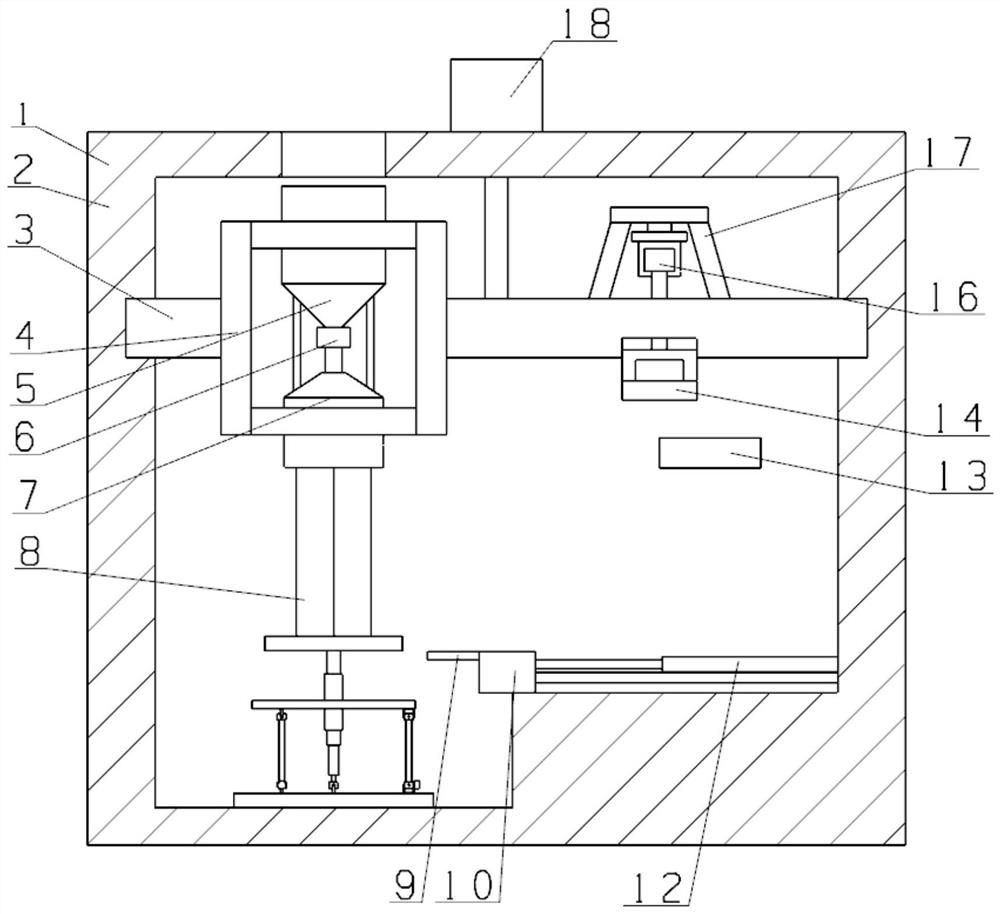
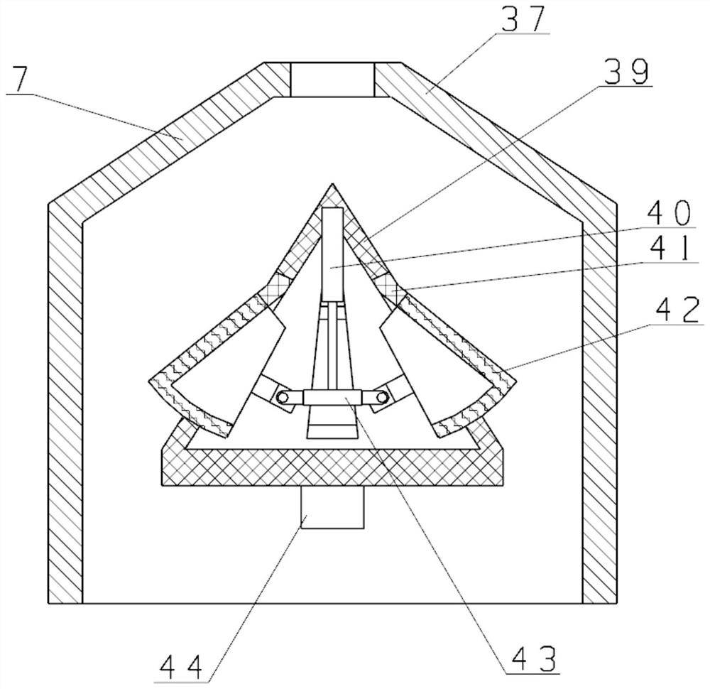
[0024] see Figure 1~Figure 7 As shown, a compact pipe-making device for concrete includes a pipe-making device 1, the pipe-making device 1 includes a frame body 2, a first motor 18 is arranged on the upper end surface of the frame body 2, and the output of the first motor 18 The shaft end is provided with a rotating plate 3, and the two ends of the rotating plate 3 are arranged in the frame body 2, and the rotating plate 3 is connected to the frame body 2 in rotation, and a square fixing frame 4 is fixedly installed on the rotating plate 3. The fixed frame 4 is provided with a material cylinder 5, the material cylinder 5 is connected with a control valve 6, and a feed pipe is arranged under the control valve 6, and the lower end of the feed pipe is fixedly connected with a speed control valve fixedly connected with the fixed frame 4. 7, the speed controller 7 includes an outer casing 37, a connecting plate 44 is connected inside the outer casing 37, an inner casing 39 is inst...

Embodiment 2

[0031] On the basis of embodiment one, refer to figure 1 , the lower right part of the frame body 2 is fixedly connected with a third electric push rod 12, a slider 10 is arranged on the third electric push rod 12, and a shovel plate 9 is fixedly installed on one side of the slider 10; The push rod 12 drives the slide block 10 so that the shovel plate 9 automatically takes out the formed concrete pipe, which saves manpower.

[0032]Working principle: In the process of use, through the setting of the feeding hopper 40, the outer shell 37, the connecting plate 44, the inner shell 39, the first electric push rod 40, the pushing block 43, the retaining plate 42, and the elastic reed 41 Cooperate with each other to block and control the falling concrete of the barrel 5. The higher the tilting angle of the baffle plate 42, the better the deceleration effect on the concrete. At the same time, the inner shell 39 can effectively divert and guide the concrete, and when the concrete flow...


PUM


Abstract

The present invention relates to the technical field of concrete molding devices, in particular to a compact pipe-making device for concrete, which includes a pipe-making device. The output shaft end of the output shaft is provided with a rotating plate, and the two ends of the rotating plate are arranged in the frame body, and the rotating plate is connected with the frame body in rotation, and a square fixing frame is fixedly installed on the rotating plate, and a barrel , the barrel is connected with a control valve, a feeding pipe is arranged under the control valve, a speed controller fixedly connected with a fixed frame is fixedly connected to the lower end of the feeding pipe, the speed controller includes an outer shell, and the A shock tube device is installed under the outer casing; the device has a high degree of automation, which facilitates smooth exhaust, improves construction efficiency, and improves the quality of finished products.

Description

technical field [0001] The invention relates to the technical field of concrete forming devices, in particular to a compact pipe-making device for concrete. Background technique [0002] Ordinary concrete refers to the artificial stone made of cement as the main cementitious material, mixed with water, sand, stones, chemical admixtures and mineral admixtures when necessary, mixed in an appropriate proportion, and uniformly stirred, compacted and cured. . Concrete is mainly divided into two stages and states: the plastic state before setting and hardening, that is, fresh concrete or concrete mixture; the hard state after hardening, that is, hardened concrete. The mutual impact with the concrete added at high speed will cause a large number of air bubbles to gather in the concrete and reduce the quality of the finished product. At the same time, the difference in the accumulation of concrete in various parts of the mold will easily occur in the process of direct pouring with ...

Claims


Application Information

Patent Timeline
Patent Type & Authority Patents(China)
IPC IPC(8): B28B21/14B28B17/00
CPCB28B21/14B28B17/00
Inventor 温林坤
Owner 杭州钱龙实业有限公司
Why Eureka
Try Eureka