
Optical glass manufacturing method

A technology of optical glass and manufacturing method, applied in the field of glass manufacturing, can solve the problems of poor coating effect, damage to optical glass, low degree of automation, etc.

Inactive Publication Date: 2021-05-28
史桂兰
View PDF3 Cites 0 Cited by
  • Summary
  • Abstract
  • Description
  • Claims
  • Application Information

AI Technical Summary

Problems solved by technology

[0005] 1. The process of manually attaching the protective film to the surface of the optical glass is long, and the efficiency of manually coating the optical glass is low due to the low degree of automation;
[0006] 2. Human hands are easy to damage the optical glass when picking up, attaching and placing the optical glass, which leads to a high defect rate when the optical glass is coated;
[0007] 3. It is difficult to accurately attach the protective film to the surface of the optical glass when manually coating the surface of the optical glass, resulting in a poor coating effect when manually coating the optical glass, thus reducing the protection of the optical glass by the protective film Effect

Method used


Image

  • Optical glass manufacturing method
  • Optical glass manufacturing method
  • Optical glass manufacturing method

Examples


Embodiment Construction

[0036] The embodiments of the present invention will be described in detail below with reference to the accompanying drawings, but the present invention can be implemented in many different ways defined and covered by the claims.

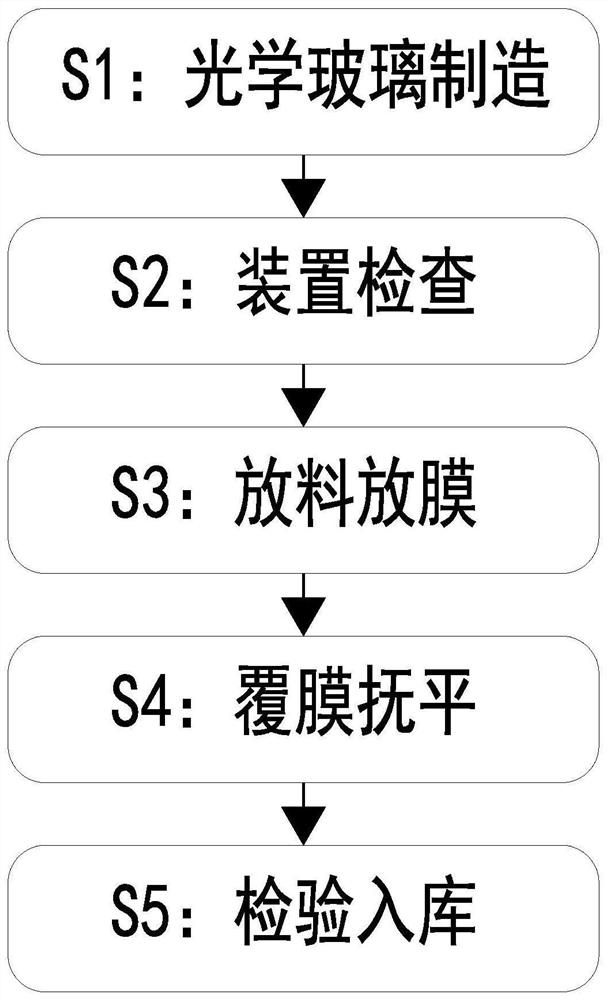
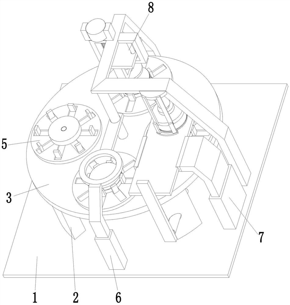
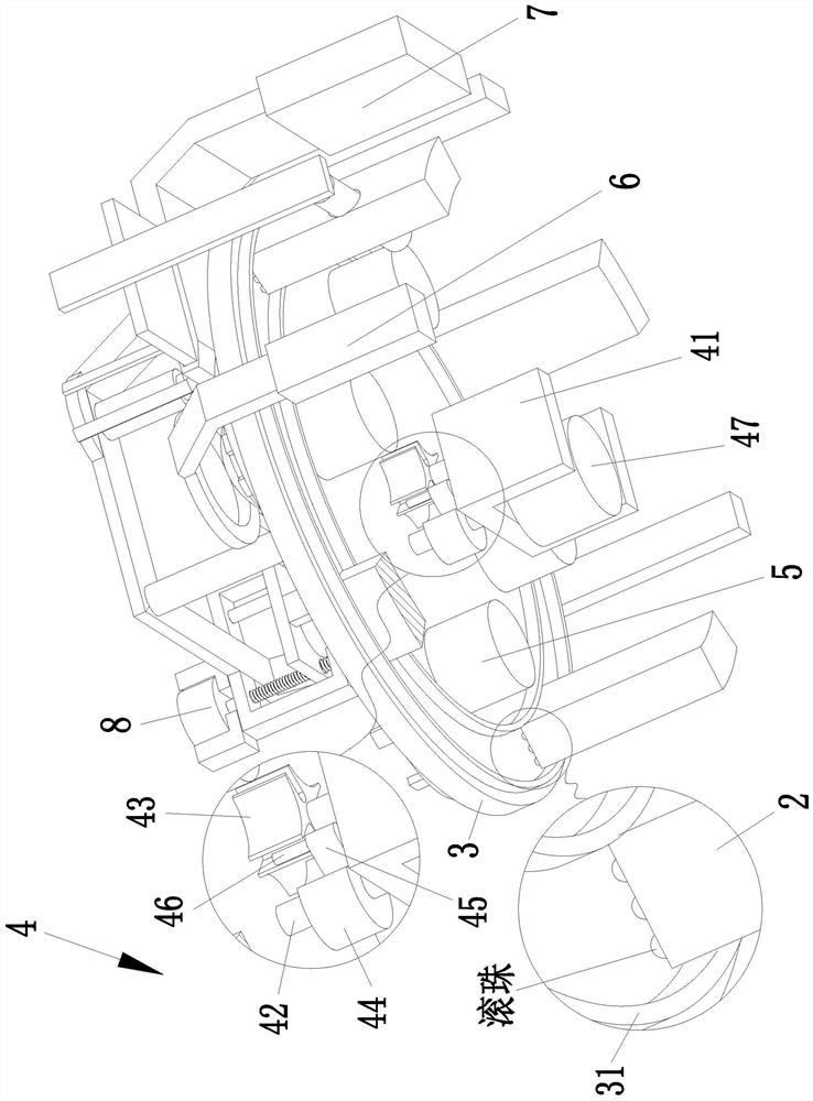
[0037] Such as Figure 1 to Figure 6 As shown, an optical glass manufacturing method, the optical glass manufacturing method adopts the following optical glass manufacturing device, the optical glass manufacturing device includes a base 1, a supporting plate 2, a supporting circular plate 3, a sheave mechanism 4, and a clamping mechanism 5 , discharge mechanism 6, film discharge mechanism 7 and film covering mechanism 8, the support plate 2 of arc-shaped structure is evenly arranged on the upper end surface of the base 1, and the support plate is provided with a supporting circular plate through rotation and cooperation between the upper ends of the support plate 2 3. The lower end of the middle part of the supporting circular plate 3 is provided wi...


PUM


Abstract

The invention relates to an optical glass manufacturing method. The optical glass manufacturing method adopts the following optical glass manufacturing device, the optical glass manufacturing device comprises a base, supporting plates, a bearing circular plate, a grooved wheel mechanism, clamping mechanisms, a discharging mechanism, a film releasing mechanism and a film covering mechanism, the upper end face of the base is uniformly provided with the supporting plates of arc-shaped structures, the bearing circular plate is arranged between the upper ends of the supporting plates in a rotating fit mode, the grooved wheel mechanism is arranged at the lower end of the middle of the bearing circular plate, the clamping mechanisms are evenly arranged at the upper end of the bearing circular plate, and the discharging mechanism, the film releasing mechanism and the film covering mechanism corresponding to the clamping mechanisms in position are sequentially arranged on the positions, located on the front side, the right side and the rear side of the bearing circular plate, of the upper end face of the base. The optical glass manufacturing method solves the problems that the film covering efficiency is low in the process of carrying out film covering treatment on optical glass in a manual mode, the optical glass is easy to damage in the film covering process, and the film covering effect is poor.

Description

technical field [0001] The invention relates to the field of glass manufacturing, in particular to an optical glass manufacturing method. Background technique [0002] Optical glass: an amorphous (glassy) optical dielectric material that transmits light. It can be used to make various optical components such as prisms, lenses, filters, etc. After the light passes through, it can change the propagation direction, phase and intensity, etc.; optical glass can be divided into three categories according to different requirements: colorless optical glass, resistant Radiation optical glass and colored optical glass, among which colorless optical glass has specific requirements for optical constants, and has the characteristics of high transmission in the visible region and no selective absorption and coloring. According to the Abbe number, it is divided into crown type and flint type glass, and each type is divided into several types according to the refractive index, and arranged...

Claims


Application Information

Patent Timeline
IPC IPC(8): B29C63/02
CPCB29C63/02B29C63/0004
Inventor 史桂兰陈响响
Owner 史桂兰
Learn More