
Water supply equipment

A technology of water supply equipment and water inlet pipes, which is applied in water/sewage treatment, multi-stage water/sewage treatment, light water/sewage treatment, etc., and can solve problems such as unfavorable users, easy scaling of tanks, and poor water storage environment

Inactive Publication Date: 2021-05-28
西安清源环保科技有限公司
View PDF0 Cites 0 Cited by
  • Summary
  • Abstract
  • Description
  • Claims
  • Application Information

AI Technical Summary

Problems solved by technology

However, since the pressure of the municipal pipe network can only reach about 0.2MPa, the water pressure and water quality of high-rise users have been plagued by the designers of the water supply company. appears, so that the above problems can be easily solved
Existing domestic water supply equipment, because after a long time of use, the inside of the tank is prone to scaling, resulting in worsening water storage environment inside the tank, and the sanitation of water resources will also become worse and worse, which is not conducive to user use

Method used


Image

  • Water supply equipment
  • Water supply equipment
  • Water supply equipment

Examples


Embodiment 1

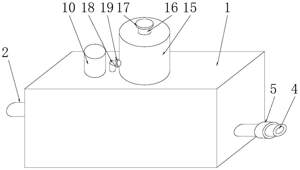
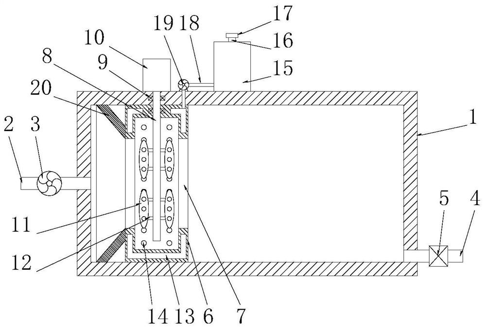
[0019] See Figure 1-2 , a water supply device, comprising a tank body 1, one end of the tank body 1 is connected to a water inlet pipe 2, and the other end of the tank body 1 is connected to a water outlet pipe 4, and a control valve 5 is installed on the water outlet pipe 4. A water inlet pump 3 is installed on the water inlet pipe 2, and a mixing cylinder 6 is provided in the inner cavity of the tank body 1. The left and right side ends of the mixing cylinder 6 are connected with a communication hole 7, and the end of the mixing cylinder 6 near the water inlet pipe 2 is provided with a The diversion bucket 20 matched with the communication hole 7, the mixing cylinder 6 is provided with a mixing shaft 8, the axis of the mixing cylinder 6 coincides with the axis of the mixing shaft 8, and the top of the mixing shaft 8 runs through the top wall and the mixing cylinder 6. The top wall of the tank body 1 is rotatably connected to the mixing motor 10, the mixing shaft 8 is rotata...

Embodiment 2

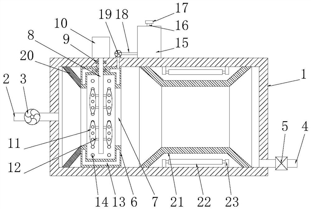
[0022] See image 3 , and the difference from Embodiment 1 is that: the inner cavity of the tank body 1 is also provided with an isolation cover 21, the isolation cover 21 is an annular structure, and the isolation cover 21 is arranged on the right side of the mixing cylinder 6, and the isolation cover 21 The unilateral cross-section of 21 is an isosceles trapezoidal structure, and the isolation cover 21 is made of transparent glass. The inner cavity of the isolation cover 21 is uniformly provided with a number of ultraviolet lamps 22, and the ultraviolet lamps 22 are fixedly installed on the tank through the feet 23. On the inner cavity wall of the tank body 1, ultraviolet rays are irradiated by the ultraviolet lamp 22, and the ultraviolet lamp tube is used to penetrate the isolation cover 21 to realize ultraviolet irradiation disinfection of the water in the tank body 1, and cooperate with the disinfection of the medicinal solution in the mixing cylinder 6, thereby further T...


PUM


Abstract

The invention discloses water supply equipment which comprises a tank body, one end of the tank body is in through connection with a water inlet pipe, the other end of the tank body is in through connection with a water outlet pipe, an inner cavity of the tank body is provided with a mixing cylinder, and the left side end and the right side end of the mixing cylinder are in through connection with communicating holes; a mixing shaft is arranged in the mixing cylinder, the top end of the mixing shaft penetrates through the top wall of the mixing cylinder and the top wall of the tank body and is rotationally connected to a mixing motor, the mixing motor is mounted at the top end of the tank body, and a plurality of mixing blades are uniformly arranged on the outer side of the mixing shaft; a medicine cavity is formed in the side wall of the mixing cylinder, and a plurality of medicine seeping holes matched with the medicine cavity are uniformly formed in the inner cavity wall of the mixing cylinder; liquid medicine in the medicine box is pumped through the medicine supply pump so that the liquid medicine is supplied to the medicine cavity through the connecting pipe, finally enters the mixing cylinder through the medicine seeping holes and is rapidly mixed under the action of the mixing blades rotating at a high speed, water in the tank body is disinfected through the liquid medicine, and thus the water supply quality in the tank body is guaranteed.

Description

technical field [0001] The invention relates to the technical field of water supply equipment, in particular to water supply equipment. Background technique [0002] Water supply equipment: a water supply device that outputs a certain flow rate and lift in a unit time and automatically starts and stops. Divided by use: fire protection, life, production, sewage treatment four categories. In recent years, with the rapid development of the economy, high-rise buildings have sprung up all over the place, standing in front of people one by one. However, since the pressure of the municipal pipe network can only reach about 0.2MPa, the water pressure and water quality of high-rise users have been plagued by the designers of the water supply company. appears, so that the above problems can be easily solved. [0003] With the development of secondary water supply pressurization technology, water supply equipment has fundamentally solved the problem of water supply from water towers...

Claims


Application Information

Patent Timeline
Patent Type & Authority Applications(China)
IPC IPC(8): C02F9/08
CPCC02F1/00C02F1/32C02F2303/04
Inventor 白小钊
Owner 西安清源环保科技有限公司
Learn More