Self-cleaning device of belt type sludge dewatering machine

A technology of sludge dewatering machine and dewatering device, applied in water/sludge/sewage treatment, sludge treatment, water/sewage treatment, etc., can solve the problems of large water consumption, increased production cost, unfavorable energy saving and emission reduction, etc. Achieve the effect of improving work efficiency, improving compactness and compact structure

Pending Publication Date: 2021-05-28
江苏康德龙环保有限公司
View PDF5 Cites 0 Cited by
  • Summary
  • Abstract
  • Description
  • Claims
  • Application Information

AI Technical Summary

Problems solved by technology

[0002] At present, the cleaning device of the belt sludge dewatering machine is cleaned by spraying water from several nozzles on the cleaning pipe. The water pressure at the outlet of the nozzle is completely generated by the high-pressure water pump into the cleaning pipe. Therefore, the water consumption is very large, and the water pressure of the high-pressure water pump must be increased. Only in this way can the cleaning effect be guaranteed, and additional clean water is used for cleaning, which increases the production cost and is not conducive to energy saving and emission reduction

Method used


Image

  • Self-cleaning device of belt type sludge dewatering machine
  • Self-cleaning device of belt type sludge dewatering machine
  • Self-cleaning device of belt type sludge dewatering machine

Examples


Embodiment 1

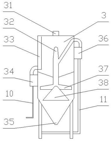
[0024] Embodiment 1, as shown in the figure: a self-cleaning device of a belt-type sludge dewatering machine, including a housing 1, the housing 1 is provided with an upper dehydration device 13 and a lower dehydration device 5, and the lower dehydration device 5 is provided. One end of the dehydration device 5 is provided with a feed plate 4, and the other end of the lower dehydration device 5 is provided with a discharge plate 12, and both sides of the feed plate 4 and the discharge plate 12 are fixed on the housing 1 Above, the upper dehydration device 13 and the lower dehydration device 5 are covered with a filter cloth 17 , and one side of the housing 1 is provided with a water filtration device 3 . The upper dehydration device 13 includes a first upper guide roller 131 , a second upper guide roller 132 , a third upper guide roller 133 , a stretching dehydration device 14 and an upper cleaning device 2 . The lower dehydration device 5 includes a first lower guide roller 5...

Embodiment 2

[0025] Embodiment 2, a self-cleaning device of a belt sludge dewatering machine, the upper dehydration device 13 and the lower dehydration device 5 are covered with a filter cloth 17 and squeezed together by the closing roller 16, and the filter cloth 17 is squeezed After being pressed together, they enter the tensioning and dehydrating device 14 through the driving wheel 15. The said tensioning and dehydrating device 14 includes a tensioning pallet 142, and the said tensioning pallet 142 includes a rising tensioning pallet 142 and a lower tensioning pallet. plate 142, two groups of tensioning groups are provided on the rising tensioning supporting plate 142, and three tensioning groups are provided on the lower tensioning supporting plate 142, and the tensioning groups include tensioning rods 145. One end of the tensioning rod 145 is provided with a tensioning plug 143, and the other end of the tensioning rod 145 is connected with the tensioning wheel 146 through a pin shaft, ...

Embodiment 3

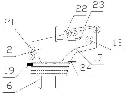
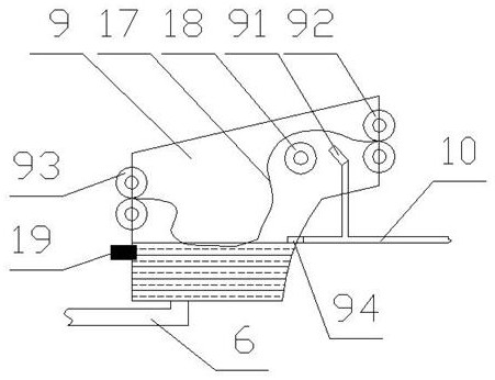
[0026] Embodiment 3, a self-cleaning device of a belt sludge dewatering machine, the upper cleaning device 2 includes a first upper squeeze roller 21 and a second upper squeeze roller 22, and the second upper squeeze roller 22 is provided with a first upper nozzle 23 below the first upper nozzle 23, and a cleaning roller 18 is arranged below the first upper nozzle 23. The inner wall of the upper cleaning device 2 is provided with a second upper nozzle 24, and the second A water level gauge 19 is provided on the inner wall of the upper cleaning device 2 corresponding to the upper spray head 24 , and the first upper spray head 23 and the second upper spray head 24 are connected to the water filter device 3 through the water spray line 10 . The lower cleaning device 9 includes a first lower squeeze roller 93 and a second lower squeeze roller 92, one side of the second lower squeeze roller 92 is provided with a cleaning roller 18, and the cleaning roller 18 is set in the lower cle...


PUM


Abstract

A self-cleaning device of a belt type sludge dewatering machine comprises a shell, an upper dewatering device and a lower dewatering device are arranged in the shell, a feeding plate is arranged at one end of the lower dewatering device, a discharging plate is arranged at the other end of the lower dewatering device, the two sides of the feeding plate and the two sides of the discharging plate are fixed to the shell, and the upper dewatering device and the lower dewatering device are both sleeved with filter cloth. A water filtering device is arranged on one side of the shell. Through the arrangement of the upper cleaning device and the lower cleaning device, cleaning of the filter cloth is achieved, and due to the fact that water used in the upper cleaning device and the lower cleaning device comes from the dewatering device, energy conservation and emission reduction are achieved, and the production cost is reduced; through the arrangement of the tensioning dewatering device, the tensioning effect on the filter cloth is achieved, the compactness of the filter cloth during passing is improved, the filter cloth can be automatically tensioned after the filter cloth is loosened, and the working efficiency is improved; and through the arrangement of the water filtering device, water generated in the dewatering equipment is filtered.

Description

technical field [0001] The invention relates to the technical field of sludge dewatering machines, in particular to a self-cleaning device of a belt type sludge dewatering machine. Background technique [0002] At present, the cleaning device of the belt sludge dewatering machine is cleaned by spraying water from several nozzles on the cleaning pipe. The water pressure at the outlet of the nozzle is completely generated by the high-pressure water pump into the cleaning pipe. Therefore, the water consumption is very large, and the water pressure of the high-pressure water pump must be increased. Only in this way can the cleaning effect be guaranteed, and cleaning with extra clear water increases the production cost and is not conducive to energy saving and emission reduction. Contents of the invention [0003] The purpose of the present invention is to address the deficiencies in the existing technology, and propose a self-cleaning device for a belt sludge dewatering machin...

Claims


Application Information

Patent Timeline
Patent Type & Authority Applications(China)
IPC IPC(8): C02F11/123C02F1/00B01D33/056B01D33/04B01D33/46B01D33/50B01D33/80
CPCC02F11/123C02F1/001B01D33/056B01D33/04B01D33/463B01D33/50B01D33/80B01D33/801B01D33/803
Inventor 黄华纪霞孙益平
Owner 江苏康德龙环保有限公司
Why Eureka
Try Eureka