Compressor air cylinder and compressor comprising same

A technology of compressors and cylinders, applied in the field of compressor cylinders, can solve the problems of reducing compressor efficiency, increasing compressor weight, material cost, suction loss, etc. Sex-enhancing effect

Pending Publication Date: 2021-05-28
SHANGHAI HITACHI ELECTRICAL APPLIANCES CO LTD
4 Cites 0 Cited by

AI-Extracted Technical Summary

Problems solved by technology

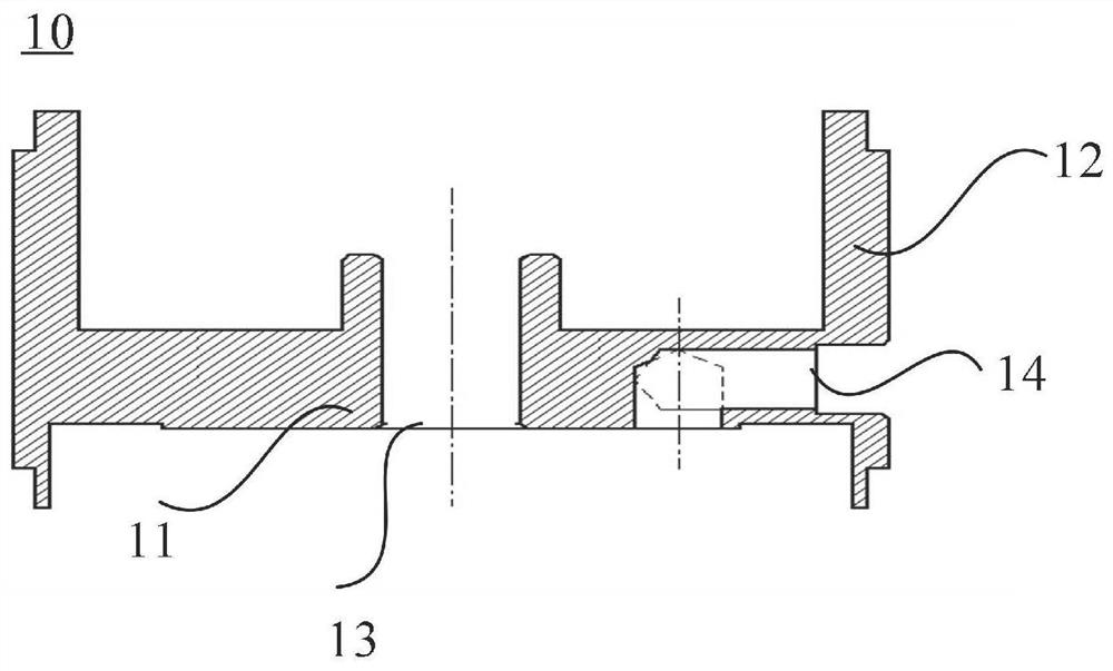
However, in this structure, the air suction hole 14 is located at the crosspiece 12 of the H-shaped frame, and the air suction channel needs to be bent when entering the cylinder. figure 1 The middle is 90°bending, the bending of the suction channel will cause suction loss, thereby reducing the efficiency of the compressor
[0004] In addition, the thickness of the crosspiece of the H-shaped frame will also be limited by...

Abstract

The invention provides a compressor air cylinder and a compressor comprising the same. The compressor air cylinder comprises an air cylinder body and a circumferential side wall formed on the outer edge of the air cylinder body; the side wall comprises a circumferential part extending upwards from the outer edge of the upper end face of the air cylinder body or/and a circumferential part extending downwards from the outer edge of the lower end face of the air cylinder body; the air cylinder body is provided with an air cylinder body working cavity penetrating through the upper end face and the lower end face of the air cylinder body; and an air suction channel is arranged in the radial direction of the air cylinder body, one end of the air suction channel is an air suction port, and the other end of the air suction channel communicates with the air cylinder body working cavity. According to the compressor air cylinder, through the integrated design of the air cylinder body and a shell, the height of the compressor is reduced while the height of the air cylinder body is reduced, the structure is compact, and the higher miniaturization requirement is met; and meanwhile, the air suction channel directly arranged at the position of the air cylinder body can effectively solve the problem of internal leakage, air inlet loss is reduced, the degree of superheat is reduced, and therefore the operation stability and efficiency of the compressor are improved.

Application Domain

Rotary piston pumpsRotary piston liquid engines +2

Technology Topic

PhysicsMechanical engineering

Image

  • Compressor air cylinder and compressor comprising same
  • Compressor air cylinder and compressor comprising same
  • Compressor air cylinder and compressor comprising same

Examples

  • Experimental program(1)

Example Embodiment

[0042]An example embodiment will now be described more fully with reference to the accompanying drawings. However, an example embodiment can be implemented in a variety of forms, and is not to be construed as being limited to the examples described herein; in contrast, the present disclosure will make the present disclosure will be more comprehensive and complete, and the concept of an example embodiment is fully conveyed A technician in the art. The features, structures, or characteristics described may be incorporated in one or more embodiments in any suitable manner.
[0043]Further, the drawings are only schematic illustrations of the present disclosure, and it is not necessarily drawn. The same reference numerals in the figure represent the same or similar portions, and thus repeats them will be omitted. Some of the block diagrams shown in the drawings are functional entities, and do not necessarily have to correspond to physical or logically independent entities.
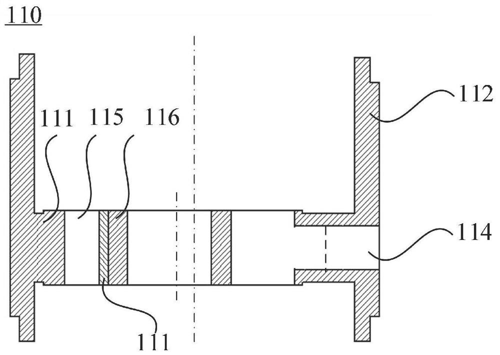
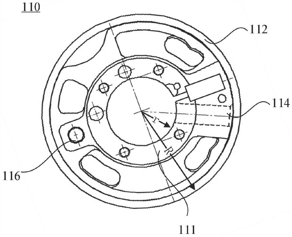
[0044]figure 2 withimage 3 A schematic diagram of a cross-sectional structure of a compressor cylinder according to an embodiment of the present invention, a schematic view of a plan view, in particular, compressor cylinder 110, respectively, includes:
[0045]The cylinder body 111 and the circumferential side wall 112 formed on the outer edge of the cylinder body; the side wall includes a circumferential portion or / and the cylinder body of the upper end surface of the cylinder body. The circumferential portion of the outer edge of the end face.
[0046]The cylinder body 111 has an upper end surface and a lower end surface cylinder body working chamber through the cylinder body;
[0047]A suction passage 114 is provided in a radial direction of the cylinder body 111, and one end of the suction passage 114 is a suction port, and the other end is in communication with the cylinder body working chamber. The suction port is used to connect to the reservoir. It should be noted that the cylinder body 111 and the side wall 112 are each two, preferably, the cylinder body, and the side wall formed on the cylinder body in the circumferential shape of the cylinder body. The materials of one-integrated mold include, but are not limited to, metal materials such as cast iron. One forming member can be achieved by casting and other methods. The integrated mold structure enables the performance of the cylinder body and the side walls of the side wall.
[0048]In the above embodiment, the suction passage 114 is a character line, that is, the intake passage 114 is not set.figure 1 The curvature of the inhalation passage 114 can be parallel to the upper end surface or lower end surface of the cylinder body 111, and can be seen as the inhalation passage 114 and the inner wall of the cylinder body 111, and the inhalation passage 114 is not limited. The central axis is formed at a certain angle to the upper end of the cylinder body 111. The entire intake passage 114 can be consistent in the center axis direction, preferably, the width of the suction passage and the height ratio of the cylinder body is m, and 0.4 ≤ m ≤ 0.9. The width of the intake passage 114 may be varied in the central axis direction.
[0049]figure 2 The side wall 112 of the embodiment includes a circumferential portion of the circumferential portion of the upper end surface of the cylinder body and the outer edge of the lower end surface of the cylinder body.
[0050]The inner radius of the cylinder body in the present invention is R, and the radius of the circumferential side wall formed by the outer edge of the cylinder body is R, seeimage 3 Preferably, the value of R / R is between 0.3 and 0.5.
[0051]Embodiments of the present invention also provide a compressor including the compressing machine cylinder described above.Figure 4EXAMPLES THE INFORMATION The micro compressor is generally referred to as a refrigeration compressor having a cooling amount of less than 1 kW. The compressor is the core of the refrigeration system, its capabilities and features determine the capabilities and characteristics of the refrigeration system, the micro-compressor has the characteristics of small volume, light weight, high power, low energy consumption, quiet and quiet frequency, and easy precise control. It is the first choice for the ideal mobile or portable small thermal management system. At present, the main applications of micro compressors include portable refrigeration systems, food cooling systems, micro-refrigerated systems, temperature control shipment containers, electronic refrigeration systems, medical imaging systems, mini cooling water systems, etc.
[0052]specifically,Figure 4The micro compressor includes a compressor body and a reservoir 900, a compressor body, and the reservoir 900 are connected by a suction port, and the compressor body includes a compressor cylinder 110, a upper casing cover 120, a lower shell cover 130, a housing The motor assembly of the cover 120 and the contents of the compressed machine cylinder 110, and the pump assembly set by the compressing machine cylinder 110 and the lower case cover 130.
[0053]Compressor cylinder 110 includes:
[0054]The cylinder body 111 and the circumferential side wall 112 formed in the outer edge of the cylinder body; the side wall 112 includes an circumferential portion extending upwardly from the outer edge of the upper end surface of the cylinder body and the outer edge of the cylinder body. The circumferential portion extends. The sidewalls extending in the two directions are connected to the upper casing cover 120 and the lower shell cover 130, respectively. Connections include, but are not limited to, welding connection, adhesive connection, and the like.
[0055]The cylinder body 111 has an upper end surface and a lower end surface cylinder body working chamber through which the cylinder body 111 is provided; one end of the cylinder body 111 is provided with a suction passage 114, one end of the suction passage 114 is a suction port, and the other end and the The cylinder body working chamber is connected. The reservoir 900 is connected to the cylinder body working chamber by the suction port 901, the suction port, the suction passage 114.
[0056]In this embodiment, the compressor further includes an upper cylinder head 140 and a socket 150 including a bolt hole 115, the upper cylinder head 140 and the lower cylinder cover 150 through the bolt hole 115 and The compressor cylinder is connected. The upper end surface of the cylinder body is connected to the upper cylinder head, and the lower end surface of the cylinder body is connected to the lower cylinder cover.Figure 4In the embodiment, the connection is fastened by a bolt.
[0057]The compressor cylinder of the present invention is not limited to a single-cylinder compressor, and is equally applicable to a double-cylinder compressor. At this time, the compressor cylinder is a cylinder in a double-cylinder compressor.
[0058]In summary, the present invention provides a compressor cylinder and a compressor including the compressor cylinder including the cylinder body and the circumferential side wall formed by the outer edge of the cylinder body; the side wall includes The circumferential portion of the outer edge of the upper end surface of the cylinder body extends upward or / and the outer edge of the lower end surface of the cylinder body; the cylinder body has an upper end surface and a lower end surface of the cylinder body. The cylinder body working chamber; an inhale passage is provided in a radial direction of the cylinder body, and one end of the suction passage is a suction port, and the other end is in communication with the cylinder body working chamber. The present application reduces the height of the cylinder body and the housing to reduce the height of the cylinder body, and satisfy higher miniaturization requirements while reducing the height of the cylinder body and the housing. Channels can effectively solve the problem of internal leaks, reduce intake loss and reduce overheating, thereby improving the stability and efficiency of compressor operation.
[0059]The above is a further detailed description of the invention in conjunction with the specific embodiments, and the specific implementation of the invention is not limited to these descriptions. It will be apparent to those skilled in the art that the present application is not limited to the details of the exemplary embodiments, and the present application can be implemented in other specific forms without departing from the spirit or basic characteristics of the present application. Therefore, in any case, the embodiments should be regarded as exemplary, and non-limiting, the scope of the present application is not the above description, and therefore, it is intended to fall in accordance with the claims All changes in the meaning and range of equivalents are covered in this application. Any reference numerals in the claims should not be regarded as the claims. In addition, it is apparent that the term "includes" does not exclude other units or steps, and the singlet does not exclude the plural. The plurality of units or means described in the device according to the claims may also be implemented by a unit or device through software or hardware. It should be understood that "lower" or "down", "down" or "up" such as "Up" is used to refer to the position shown in the exemplary embodiment to describe these characteristics; first, second words To represent names, do not represent any specific order.

PUM

no PUM

Description & Claims & Application Information

We can also present the details of the Description, Claims and Application information to help users get a comprehensive understanding of the technical details of the patent, such as background art, summary of invention, brief description of drawings, description of embodiments, and other original content. On the other hand, users can also determine the specific scope of protection of the technology through the list of claims; as well as understand the changes in the life cycle of the technology with the presentation of the patent timeline. Login to view more.

Similar technology patents

Control system and method for motor vehicles

InactiveUS20040084002A1improve reliabilityspeed and stability
Owner:TOYOTA JIDOSHA KK

Installation management method, server and terminal for application program

InactiveCN102446106Aprevent crackingImprove reliability
Owner:LENOVO (BEIJING) CO LTD

Forest fireproof monitoring and patrolling system

Owner:内蒙古亨利新技术工程股份有限公司

Unmanned aerial vehicle flight control system having multisensor redundant backup

ActiveCN105867414AIncrease flight control weight and costImprove reliability
Owner:ZHEJIANG UNIV

Classification and recommendation of technical efficacy words

  • Improve reliability

Multiple branch predictions

ActiveUS20050268075A1improve reliabilityfacilitate availability
Owner:ORACLE INT CORP

Implantable lead

ActiveUS20100137928A1good flexibility , fatigue resistance and flex lifeimprove reliability
Owner:WL GORE & ASSOC INC
Why Eureka
Try Eureka