Burner and gas cooker with same

A burner, gas outlet technology, applied in burners, gas fuel burners, combustion methods, etc., can solve problems such as ignition time delay and affect user experience, achieve fast ignition, enhance user experience, and improve contact. effect of probability

Active Publication Date: 2021-05-28
NINGBO FOTILE KITCHEN WARE CO LTD
View PDF17 Cites 0 Cited by
  • Summary
  • Abstract
  • Description
  • Claims
  • Application Information

AI Technical Summary

Problems solved by technology

[0004] The technical problem to be solved by the present invention is to provide a burner and a gas cooker containing it in order to overcome the defects that the ignition time of the gas cooker in the prior art is delayed and affect the user experience

Method used


Image

  • Burner and gas cooker with same
  • Burner and gas cooker with same
  • Burner and gas cooker with same

Examples


Embodiment 1

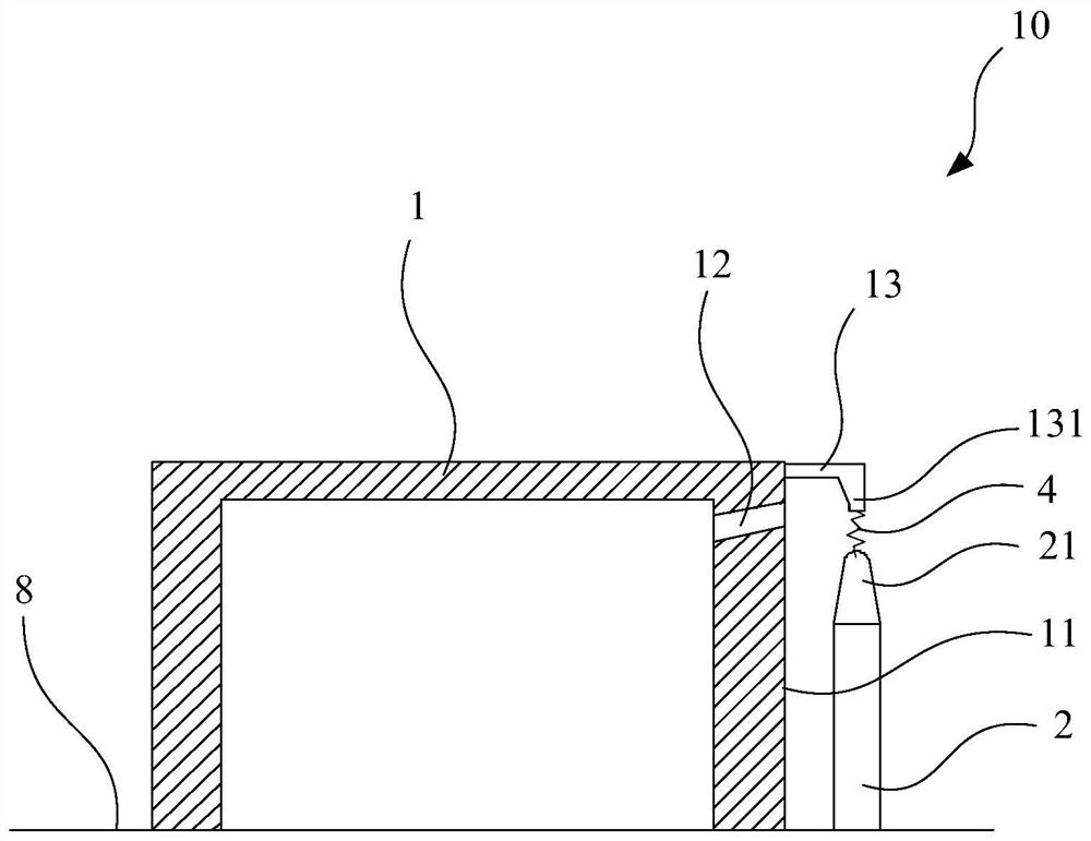
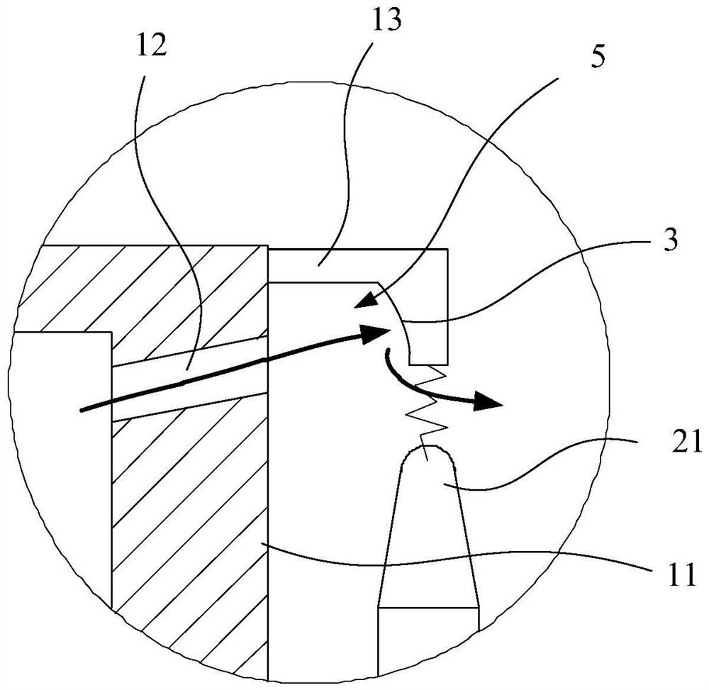
[0074] The present invention provides a gas cooker, which includes a burner 10 arranged on a cooker table 8 . Such as figure 2 As shown, the burner 10 includes a fire cover 1 and an ignition needle 2. On the surface of the fire cover 1, there is a gas outlet 12 corresponding to the ignition end 21 of the ignition needle 2, wherein the ignition end 21 is formed on the ignition needle 2. At the uppermost position, the fire cover 1 has a protruding portion 13 protruding from the outer surface 11 of the fire cover 1 above the ignition end 21, and the protrusion 13 extends to the top of the ignition end 21 along the horizontal direction, and close to the firing end 21, while, as image 3 As shown, the burner 10 also has a flow guiding structure 3 , which can guide the gas flowing out of the gas outlet 12 to flow through the area between the ignition end 21 and the protruding part 13 . In this embodiment, the flow guiding structure 3 is an arc-shaped surface formed on the protrud...

Embodiment 2

[0082] This embodiment also provides a burner 10 for a gas cooker, and the structure of the burner 10 is similar to that of the first embodiment. Specific as Figure 4-Figure 6 As shown, the burner 10 of this embodiment is an anti-dry burner, wherein the anti-dry burner specifically includes a fire cover 1 , an anti-dry sensor 6 and an energy gathering ring 9 . Wherein, the inner ring of the fire cover 1 is arranged around the anti-dry sensor 6, and the energy gathering ring 9 is arranged around the outer ring of the fire cover 1, and a pot support structure is integrated on the energy gathering ring 9.

[0083] The detection part 61 of the anti-dry heating sensor 6 is arranged higher than the inner ring top surface 17 of the fire cover 1, so as to ensure that the detection part 61 can be in contact with the bottom surface of the pot. The fire cover 1 forms a cavity 15 for accommodating the dry-burn prevention sensor 6 inside the inner ring part, and the burner 10 also includ...


PUM


Abstract

The invention discloses a burner and a gas cooker with the same. The burner comprises a burner cap and an ignition needle, the surface of the burner cap is provided with gas outlets corresponding to ignition ends of the ignition needle, the ignition ends are formed at the uppermost end of the ignition needle, the burner cap is provided with a protruding part protruding out of the outer side surface of the burner cap, and the protruding part extends to and is close to the ignition ends. The burner is provided with a flow guide structure, and the flow guide structure can guide gas, flowing out of the gas outlets, to flow through the area between the ignition ends and the protruding part. According to the burner, the protruding part close to the ignition ends is arranged on the outer side surface of the burner cap, and therefore the ignition ends discharge towards the protruding part during ignition, and the path of electric sparks generated by discharging cannot be perpendicular to the outer side surface of the burner cap. Meanwhile, the flow guide structure is arranged to guide and change the flowing direction of the gas, the gas is made to flow towards the area between the protruding part and the ignition ends, the path of the electric sparks is approximately perpendicular to the flowing direction of the gas, and the contact probability of the gas and the electric sparks is increased.

Description

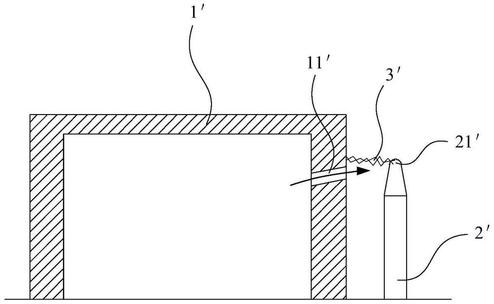
technical field [0001] The invention relates to a burner and a gas cooker containing the burner. Background technique [0002] The current gas cooker usually uses an ignition needle to ignite. The top of the ignition needle is the ignition end. The spark will burn in contact with the gas flowing out of the fire hole on the fire cover to achieve the purpose of ignition. [0003] Such as figure 1 As shown, the electric spark 3' produced by the discharge of the ignition end 21' relative to the outer surface of the fire cover 1' travels along the direction perpendicular to the outer surface, and the gas flowing out of the fire hole 11' is also close to the vertical outer surface. The directions are close, and the staggered area is small. The path through which the flame hole 11' generates the electric spark 3' at the ignition end 21' can provide a lower gas concentration, resulting in a lower success rate of ignition. Therefore, when the ignition is just started, it is neces...

Claims


Application Information

Patent Timeline
IPC IPC(8): F24C3/08F24C3/10F23D14/46F23D14/70
CPCF24C3/103F24C3/085F23D14/46F23D14/70
Inventor 邵海忠徐强
Owner NINGBO FOTILE KITCHEN WARE CO LTD
Why Eureka
Try Eureka