Moving magnet type absolute position detection device and method

A technology of absolute position and detection device, which is applied in the direction of using electric/magnetic device to transmit sensing components, can solve the problems of increasing system cost, unable to meet the number distinction of multiple moving components, and complicated control system structure.

Active Publication Date: 2021-05-28
HARBIN INST OF TECH
View PDF7 Cites 4 Cited by
  • Summary
  • Abstract
  • Description
  • Claims
  • Application Information

AI Technical Summary

Problems solved by technology

[0003] In industrial production, conventional grating scales or magnetic scales are used for linear displacement measurement, the cost is relatively high, and the sensor reading head is fixedly installed on the moving component, and the power supply and communication cables connected to the reading head will directly affect the motion unit. Motion stroke and performance, the layout of cables will complicate the structure of the control system and increase the cost of the system
In an industrial production system where multi-movement components cooperate, multiple sensors need to be used for position positioning and measurement. Conventional sensors cannot be uniquely numbered on the hardware, and cannot be flexibly configured and used
Patent CN 101915590B proposes a magnetoresistive array-based position detection system, which obtains the position of the motion unit by processing the une

Method used


Image

  • Moving magnet type absolute position detection device and method
  • Moving magnet type absolute position detection device and method
  • Moving magnet type absolute position detection device and method

Examples


Embodiment Construction

[0031] The technical solutions and implementation methods in the embodiments of the present invention will be described in detail below with reference to the drawings in the embodiments of the present invention.

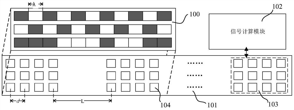
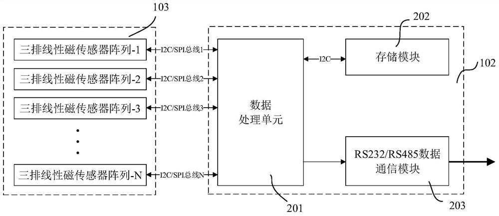
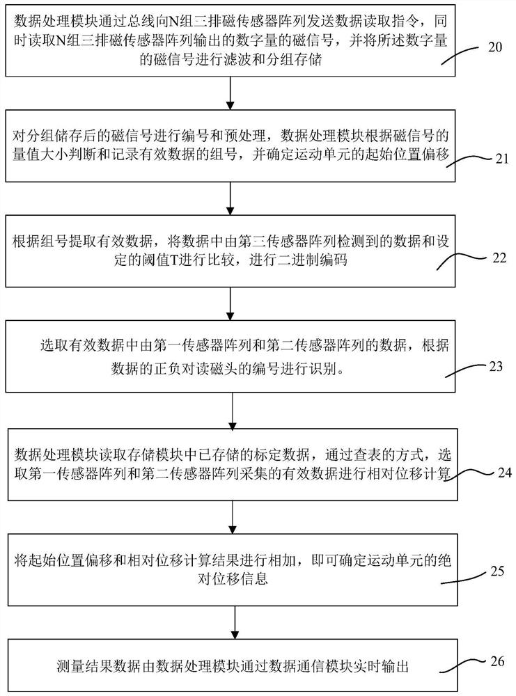
[0032] figure 1 The structural layout diagram of the example structure of the moving magnet type absolute position detection device provided by the present invention, figure 2 It is a functional block diagram of the signal calculation module in the moving magnet absolute position detection device provided by the present invention. image 3 Calculation flow chart of the moving magnet absolute displacement measurement method provided by the present invention.

[0033] A moving magnet absolute position detection device, the device in this embodiment includes a moving magnetic head 100 , a sensor acquisition board 101 and a signal calculation module 102 .

[0034] The moving magnetic head 100 is fixedly installed on the moving component to be detected for absolute dis...


PUM


Abstract

The invention relates to a moving magnetic type absolute position detection device and method. The detection device comprises a moving magnetic head, a sensor acquisition board and a signal calculation module, the moving magnetic head is installed on a moving component at a to-be-detected position, linearly moves along with the moving component, and is composed of three rows of permanent magnet arrays formed by combining a plurality of permanent magnets according to a specific coding and arrangement mode. The sensor acquisition board is fixed below the moving magnetic head in parallel, provides a position reference and consists of a plurality of groups of three rows of linear magnetic sensor arrays which are arranged at equal intervals; and the signal calculation module is composed of a data processing unit, a storage module and a data communication module, collects signals of the magnetic sensor in real time and calculates absolute displacement information. According to the device, absolute position detection and unique coding can be carried out on the detected moving component under the condition of no cable constraint, the flexibility and the movement stroke of the position detection device are improved, displacement measurement and subdivision are carried out by adopting the three-axis linear magnetic sensor array, the measurement precision of the device is improved, and the cost is saved.

Description

technical field [0001] The invention belongs to the field of position detection, and in particular relates to a moving magnet absolute position detection device and method. Background technique [0002] In the field of intelligent manufacturing, the automatic production, processing, assembly and manufacturing of products depend on the precise positioning and feedback of position detection sensors in the control system. The structure and performance of the sensors directly affect the production efficiency and product quality of the automation system. In linear displacement measurement, the most commonly used is the position detection method using grating scale and magnetic scale. The grating ruler is a displacement measuring device made using the principle of light interference and diffraction. It is widely used in precision measurement and closed-loop servo control systems due to its advantages of high measurement accuracy, fast response speed and long life. The magnetic sc...

Claims


Application Information

Patent Timeline
IPC IPC(8): G01D5/14
CPCG01D5/14
Inventor 王雷张桢徐永向
Owner HARBIN INST OF TECH
Why Eureka
Try Eureka